Aux control port, 4 connecting auxiliary devices – Crown Audio PSI User Manual
Page 11
Page 11
IQ–PSI IQ Pocket Serial Interface
models this could be +8.5 to +15 VDC, depending on
VDC, depending on
VDC, depending on
VDC, depending on
VDC, depending on
the specific power adapter provided by the user.
the specific power adapter provided by the user.
the specific power adapter provided by the user.
the specific power adapter provided by the user.
the specific power adapter provided by the user. A
total of 10 milliamps of current is available. An internal
1.0 K ohm resistor protects against shorts.
Fig. 3.10 The Internal AUX Port Circuit
patible UART.
• Do not use twisted-pair wire for RS232 cables
because the unbalanced wiring of RS232 is sus-
ceptible to crosstalk. Instead use an untwisted
cable or ribbon cable.
• If the host computer fails to communicate with
the
IQ–PSI and the baud rates are set the same,
try reducing the baud rate of both the
IQ–PSI
and the computer.
• If communication problems persist, check the
serial cable for damage.
• For further assistance, call Crown’s Technical
Support Group at 1-800-342-6939.
3.4 Connecting Auxiliary Devices
The auxiliary feature connector (AUX port) provides the
means to interface the
IQ System
to non-IQ compo-
nents. It can be used to turn another device on/off, send
a signal to another component and receive a signal from
another component.
AUX
CONNECTOR
GND
INTERNAL AUXILIARY
CIRCUITRY
INPUT
OUTPUT
1 K ohm
2 K ohm
IN OUT
TO
MICROPROCESSOR
1 K ohm
9 VDC
FROM
MICROPROCESSOR
The AUX connector is a 3-pin male “Euro-style” connec-
tor that accepts a screw-terminal plug (provided). The
first and last pins are used to send a signal and first and
second pins are used to receive a signal
.
The circuit
diagram in Figure 3.10 shows the internal AUX circuit.
3.4.1 AUX Output
When the auxiliary feature is turned on by the
IQ System
software, +10 VDC is supplied across the ground and
output pins for domestic units using an external power
adapter (+9 VDC if battery power is used). For export
AUX
CONNECTOR
GND
+8.5 to 15 V
Not Used
AUXILIARY
EQUIPMENT
110 VAC
SOLID
STATE
RELAY
(D 8063-6)
+
–
Note: The actual output
voltage of the AUX con-
nector will depend on
the power source of the
IQ–PSI.
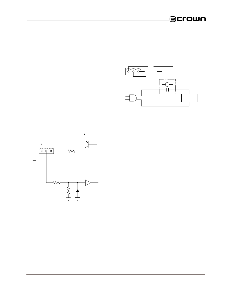
Fig. 3.11 A Sample AUX Output Circuit
There are many possible uses for the AUX output, lim-
ited only by imagination. For example, it can be used to
turn on auxiliary cooling fans. To do this the AUX con-
nector would be used to close a relay. The relay would
then turn the fans on or off. This is shown in Figure 3.11
below.
Note: A Crown part number is provided in the above
illustration for a suitable solid-state relay (D 8063-6). Con-
tact your local Crown (or Amcron
®
) representative or the
Crown factory Parts Department (219-294-8200) to order
this relay.
By monitoring the operating condition of amplifiers with
the
IQ System software, the need for additional cooling
will be apparent. The same software could then be used
to turn on the appropriate AUX connector. (For more in-
formation about turning the auxiliary feature on/off, con-
sult the IQ software
User’s Manual.)
In addition to the preceding examples, the AUX ports of
more than one IQ component can be used to send bi-
nary codes to auxiliary equipment. For example, eight
AUX ports can be used to send 8-bit binary codes to
external equipment.
3.4.2 AUX Input
Depending on the IQ software being used, the AUX con-
nector can sense the presence of an input signal across
the ground and input pins. A 5 to 30 VDC signal at the
input will be interpreted as a logic “high” and will be
communicated to the Crown Bus where a host computer
can act upon it. A signal less than 5 VDC is interpreted
as a logic “low.”
Note: A negative signal is interpreted as
a logic low because the signal is internally clipped to
protect the internal circuitry.