P.i.p.’s, Fig. 3.4 compressor threshold settings – Crown Audio P.I.P.-EDCb User Manual
Page 7
P.I.P.–EDCb
Page 7
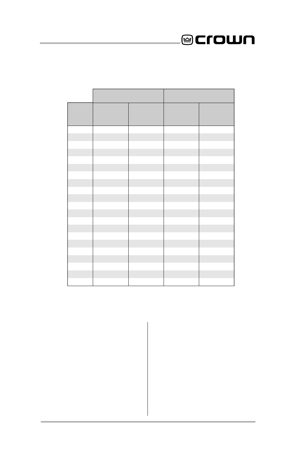
pot has a scale with ten marks
(or settings) which correspond
to the typical thresholds
shown in Figure 3.4.
4. Move the
P.I.P.’s
tracking
jumper
(Z1) to the “ON” posi-
tion to make the compressors
track each other. In the “OFF”
position, each compressor will
operate independently (refer
to Figure 2.1, “D”).
Mark
Max Sine
Wave RMS
Voltage
Watts into
8 Ohms
13.5
14
14.5
15
16
17
18
19
20
22
24
26
29
32
37
42
48
57
70
92
96
23
25
26
28
32
36
41
45
50
60
72
85
105
128
171
220
288
406
612
1058
1152
0
1
2
3
4
5
6
7
8
9
10
Macro-Tech 3600VZ and
36x12 (Channel 1)
All Others
9.5
10
10.5
11
11.5
12
13
14
15
16
17
19
21
23
26
30
35
41
50
71
102
Max Sine
Wave RMS
Voltage
Watts into
8 Ohms
11
12
14
15
17
18
21
25
28
32
36
45
55
66
85
113
153
210
313
630
1300
Fig. 3.4 Compressor Threshold Settings
3.2 Installation Procedures
You may need a phillips screw-
driver to remove the existing
P.I.P. module or panel from your
amplifier.
CAUTION:
Before connecting
this or any
P.I.P. to your ampli-
fier, it is important to turn its
level controls down, turn it off