4 technical information – Crown Audio IQ-INT3 User Manual
Page 13
Page 13
IQ-INT 3 IQ Interface
IQ-INT 3 Reference Manual
4 Technical Information
The purpose of the IQ-INT 3 is to provide a means for
the IQ System host computer to communicate with the
IQ components. The interface supports the RS232
serial data standard. It accepts host computer com-
munication rates from 9,600 to 115,200 baud, and can
drive up to four independent IQ Bus loops for a high
level of fault tolerance. In addition, the IQ-INT 3 sup-
ports both the original IQ System and the newer IQ
2
(Ucode) protocols, and it provides Crown’s own robust
network transport layer.
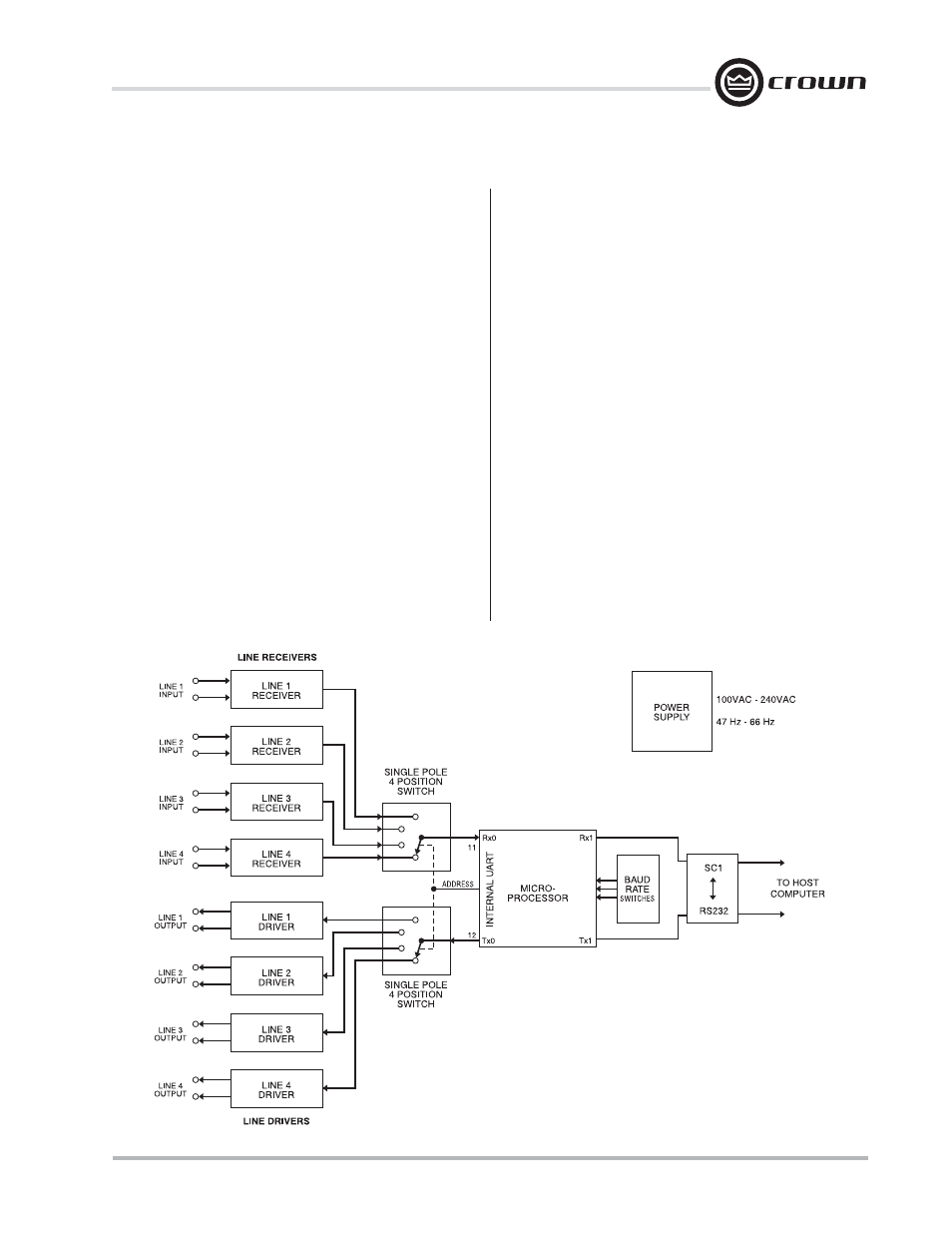
Figure 4.1 shows a block diagram of the IQ-INT 3.
The interface is equipped with an auto-reset feature.
The microprocessor generates an auto-reset signal
that can be used as a reliable power-on reset and an
automatic “warm” reset in case control is lost due to
noise or other anomalies.
The baud rate for communication with the host com-
puter is determined by the baud rate generator which
is controlled by a four-segment DIP switch (SW1).
The interface’s microprocessor communicates with
other IQ components using its internal UART to drive
each loop at 38,400 baud.
Data from the host computer arrives at the IQ-INT 3
serial port which accepts the RS232 data standard.
From here the signal goes to the serial input, Sci1 (Rx)
of the microprocessor. Next, the interface takes care of
any required checksum calculations and other trans-
port layer processing. Finally, all of the data bytes are
dumped out the microprocessor’s Sci0 port (the Tx.
pin) at 38,400 baud.
The microprocessor controls the input and output se-
lectors that control which loop will receive data. Data
sent to the selected line driver, which sends the data
onto the current loop to the appropriate IQ component.
The line receiver takes incoming data from IQ compo-
nents and sends it through the input selector to the
microprocessor’s Sci0 input Rx. pin. The microproces-
sor stores the data in memory and handles the re-
quired transport layer processing. The remaining
protocol data is then sent to the serial output buffer for
transmission to the host computer via the Sci1 (Tx.)
pin.
Figure 4.1 IQ-INT 3 Block Diagram