Crown Audio IQ-INT3 User Manual
Page 10
Page 10
IQ-INT 3 IQ Interface
IQ-INT 3 Reference Manual
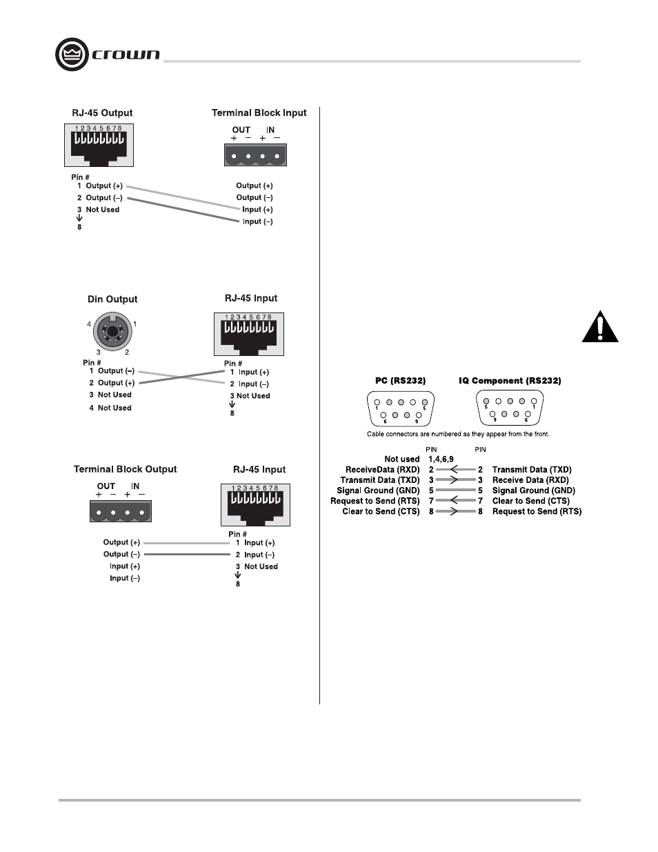
Figure 3.7 Terminal Block Output to RJ-45 Input
Figure 3.6 Din Output to RJ-45 Input
The IQ components on each IQ Bus loop are con-
nected in succession. Each loop begins and ends with
the IQ-INT 3. The output of the interface connects to
the input of the first unit, then each unit’s output is
connected to the next unit’s input until the loop returns
to the interface. This is shown in Figure 3.9.
Figure 3.8 RS232 Cable Wiring
Figure 3.5 RJ-45 Output to Terminal Block Input
3.2 Connecting to a Host Computer
RS232 is the communication standard supported by
the IQ-INT 3 for serial communication with a host com-
puter.
RS232 is commonly used with IBM
®
PCs and com-
patibles. Because it uses unbalanced signal wiring, it
cannot be used for distances over 50 feet (15.2 m).
You can use an RS232-to-RS422 adapter for serial
communication across distances of greater than 50
feet (15.2 m). Contact the Crown Technical Support
Group if you need more information about using an
RS232-to-RS422 adapter.
Figure 3.8 shows how to connect the IQ-INT 3 to the
host RS232 serial port.
IMPOR
IMPOR
IMPOR
IMPOR
IMPORT
T
T
T
TANT
ANT
ANT
ANT
ANT::::: The host computer serial interface must
have a 16550-compatible UART.
3.2.1 Connecting to a Modem
The IQ-INT 3 is also modem compatible. The IQ-INT3
periodically sends out an “AT” command string
{ATS0=1} that automatically initializes a connected
modem to its max baud rate and auto-answer mode.
A standard null modem cable should be used be-
tween the interface and modem. Refer to the diagram
in Figure 3.10 for modem wiring detail. Figure 3.11
shows an example IQ System with a modem.