2 installation procedures, P.i.p.–beq page 13 – Crown Audio P.I.P.-BEQX User Manual
Page 13
P.I.P.–BEQ
Page 13
Next, insert the edge connector of
the
P.I.P.–BEQ into the PIP2 input
adapter (see Figure 3.19) and in-
A
B
B
A
18 PIN (B)
20 PIN (A)
Q43528-1
FROM AMPLIFIER
P.I.P.
MODULE
BACK PANEL
OF PIP2
AMPLIFIER
PIP2 CONNECTOR
BOARD
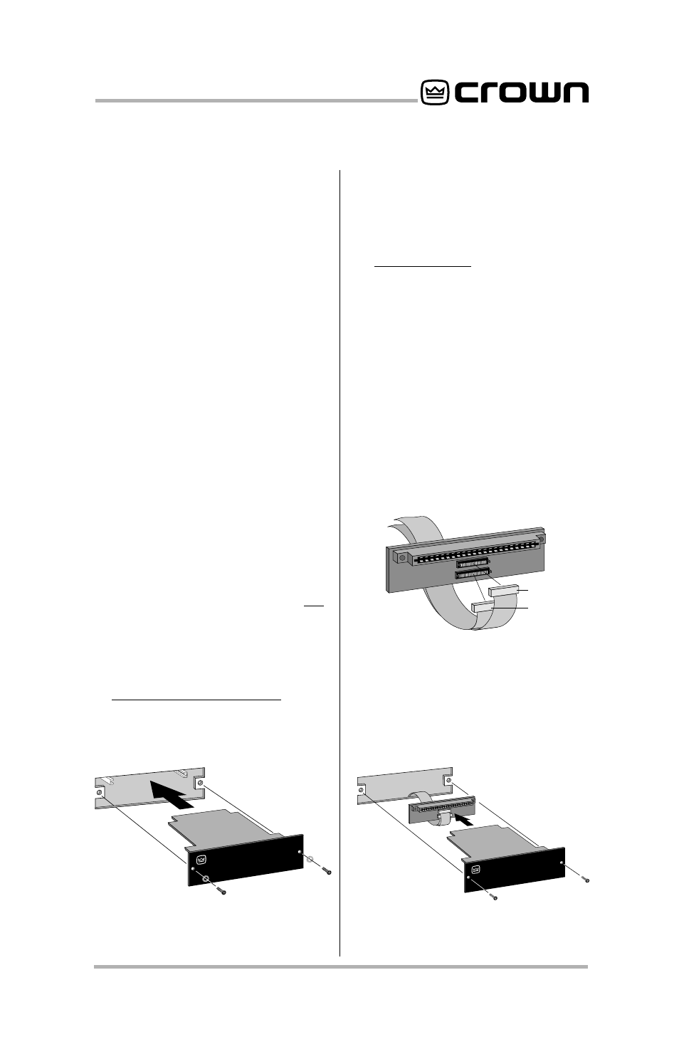
Fig. 3.18 PIP2 Input Adapter
Connection
Fig. 3.19 Installation into a
PIP2 Amplifier
3.2 Installation Procedures
You may need a phillips screwdriver
to remove the existing
P.I.P. module
or panel from your amplifier.
CAUTION:
Before connecting this
or any
P.I.P. to your amplifier, it is
important to turn its level controls
down, turn it off and remove the AC
power. Don’t touch the circuitry.
Even though the amplifier is off,
there could still be enough energy
remaining to cause electric shock.
1. Turn down the level controls (full
counterclockwise), turn off the
amplifier and unplug it from the
AC power source.
2. Remove the existing
P.I.P. mod-
ule or panel (two screws). For
PIP2 amplifiers, this may involve
disconnecting the
P.I.P. from a
PIP2 input adapter (see Figures
3.18 and 3.19). If a
PIP2 input
adapter is already present, do not
remove the ribbon cables from
the adapter. Otherwise you will
have to reconnect them in the
next step.
3.
Standard P.I.P. Amplifiers: Align
the edges of the
P.I.P.–BEQ in the
P.I.P. card rails and firmly push
P.I.P.
MODULE
BACK PANEL
OF AMPLIFIER
the unit in until it is seated against
the mounting bracket (see Figure
3.17).
PIP2 Amplifiers: (Requires a PIP2
input adaptor. Crown part num-
ber Q43528-1.) Connect the
PIP2
input adapter to the two input
cables of the amplifier (see Figure
3.18). Notice that the
PIP2 input
adapter should be positioned
with the
P.I.P. edge connector on
top and facing away from the am-
plifier. The 20 pin cable (A) is con-
nected first then the 18 pin cable
(B) is connected. Both ribbon
cables should extend below the
PIP2 input adapter.
Fig. 3.17 Installation into a
Standard P.I.P. Amplifier