Installation, Page 8 – Crown Audio PIP-BLU Module User Manual
Page 8
Networked PIP Series
Reference Manual
page 8
Installation
Before beginning, please carefully note:
CAUTION: STATIC ELECTRICITY MAY DAMAGE THE UNIT. Use caution
when handling the unit. Carefully ground yourself BEFORE touching the unit. Avoided
unnecessary touching the components or solder pads on the circuit board. It is best to
handle the unit by its front panel only.
Prepare the PIP
The PIP comes ready to install in the amplifier. This unit does not require setting the “IQ
address” as the older current loop, Crown bus, units did. Each PIP (as well as all network
components) comes preprogrammed with a unique network (MAC) address. The HiQnet
address is then set (automatically or manually) via SystemArchitect control software (TCP/
IP network address).
Prepare the Amplifier
Turn down the amplifier level controls (full counterclockwise) and turn off
the amplifier.
Disconnect the amplifier’s power cord.
Remove the existing PIP module from the amplifier back panel (two screws).
Install the PIP into the Amplifier.
Carefully ground yourself to the chassis of the amplifier before installing the
PIP, it is a good idea to maintain ground contact between yourself and the amplifier while
inserting the module into the amplifier.
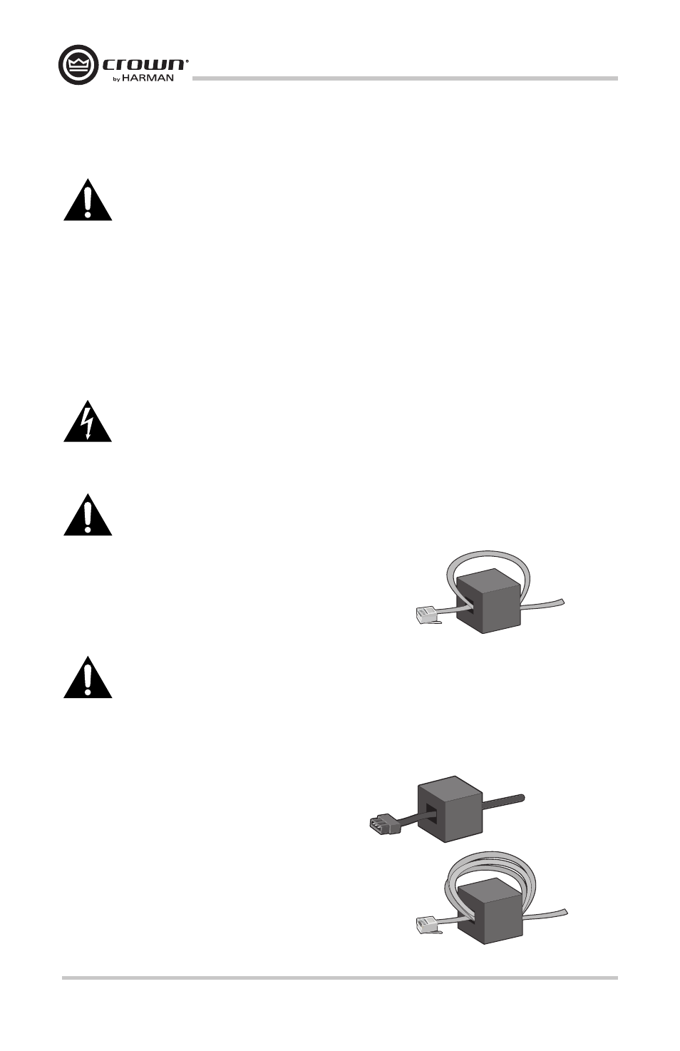
Prepare the Cables
Before using the AUX port, and after the PIP-Lite module
has been installed into the amp, make sure to pass the
CAT5 cable twice through the supplied ferrite core.
Important: On CTs3000 and CTs2000 models, make sure to add the supplied ribbon
cable ferrite core to the end of the B cable before connecting to the PIP module. Its location
will be similar to the ferrite on the A cable, with ½ to 1 inch of cable between the connector
and ferrite core. The core is not required on CTs600 and CTs1200 amplifiers.
Before using the PIP-USP4-CN, after it is installed into the amp, make sure to use ferrite
cores for cables connecting to the Analog, AES, AUX and Network ports as follow:
1. Pass all the Analog Input and Output cables
through a ferrite core (one time).
2. Pass the AES, AUX and Network cables
three (3) times through a ferrite core.
Use a separate core of each the cables.