Factory Direct Hardware Von Duprin 9847EOF3 User Manual
Page 4
4
5
5
5
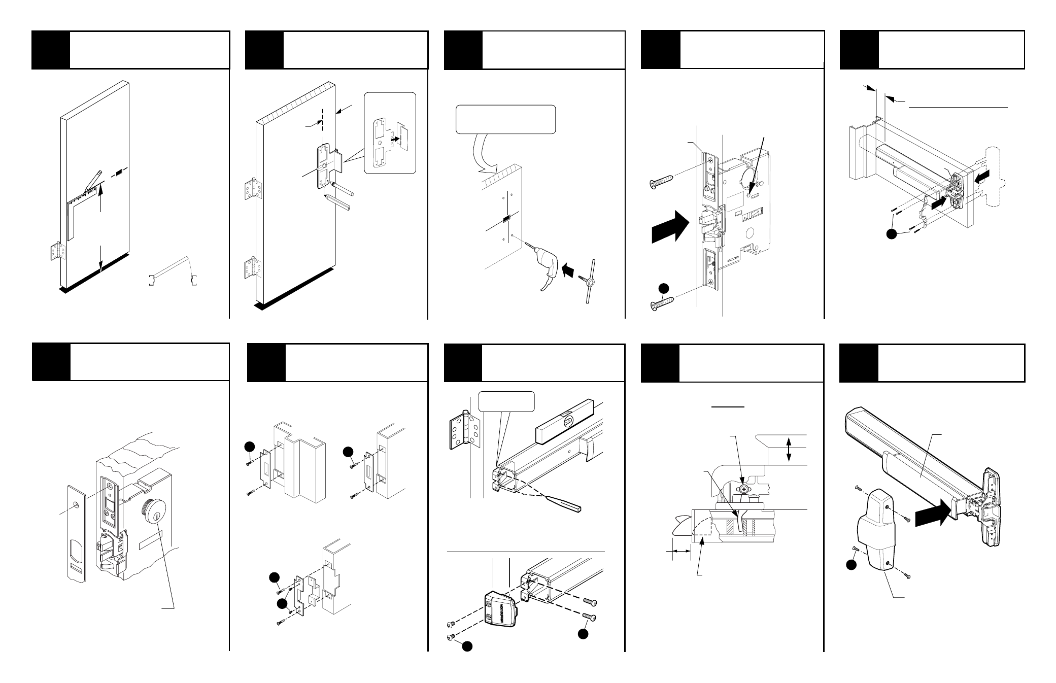
1
2
3
4
6
9
7
8
9
10
Install supplied strike to
frame or other door.
See “Strike Preparation” on page 3
for preparation information
RHR Shown
(LHR Opposite)
CL
39-5/8”
to finished
floor
Align template along center
line (C
) and mark door.
CL
Prepare 4 center case
holes and cutouts.
See “Preparation Chart”on page 3 for drill,
tap, and cut-out information
Install mortise lock
into door.
Mortise lock
Install trim (if using) and secure
device center case to door.
Install outside locking cylinder
(if using) and finish installing
mortise lock.
See 7500 Mortise Lock Instructions #941019
Outside locking
cylinder
Draw horizontal device
center line (C
).
L
See “#941019, 7500 mortise lock instructions”
Install center case cover.
Center case
cover
575 Strike
(single door
application)
575/575-2 Strike
(double door
application)
576A/576B Strike
(double door
application)
L
2-3/4”
Backset
C
See “Screw
Chart” on page 2
for screw types
and sizes
A
C
C
D
B
G
Adjust latch bolt.
Adjustment
screws
Pushbar
Top view
Adjustment
finger
Latch bolt
Loosen adjustment screws and adjust
finger in or out until latchbolt is fully
retracted (with pushbar down) and fully
extended 3/4” (with pushbar up)
3/4”
Install mounting bracket
and end cap.
Secure
mounting bracket
and end cap
Mounting
bracket flush
Level device
Mark and prepare 2
mounting holes
See “Preparation Chart” on page 3
for preparation information
E
F
Remove protective
film from pushbar
Device
template
Mark 4 holes
Mark
vertical CL
X
X
See trim instructions for
pull side door preparation.
Trim
(optional)
1-1/2” Minimum clearance
(with endcap removed)
if device is too long for
door, see “Cut Device”
on back cover
center
case
With TP, K, and L trims with outside
cylinder to lock and unlock trim function,
turn this set screw all the way in
With EO, DT, NL, and “double
cylinder” applications, screw
remains as shipped