Factory Direct Hardware Von Duprin 9847EOF3 User Manual
Installation instructions, Von duprin, Series mortise exit device
Installation Instructions
®
98/9975
Series Mortise Exit Device
This product is covered by the
following patent numbers:
3,767,238 4,427,223
3,854,763 4,466,643
4,167,280 4,741,563
911374_00(3) © 2006 Ingersoll-Rand Company Limited
Devices covered by these instructions:
98/9975 Mortise Exit Device
98/9975-F (Fire) Mortise Exit Device
CD98/9975 (Cylinder Dogging) Mortise Exit Device
EL98/9975 (Electric Latch Retraction) Mortise Exit Device
98/9975-2 (Double Cylinder) Mortise Exit Device
911374-00
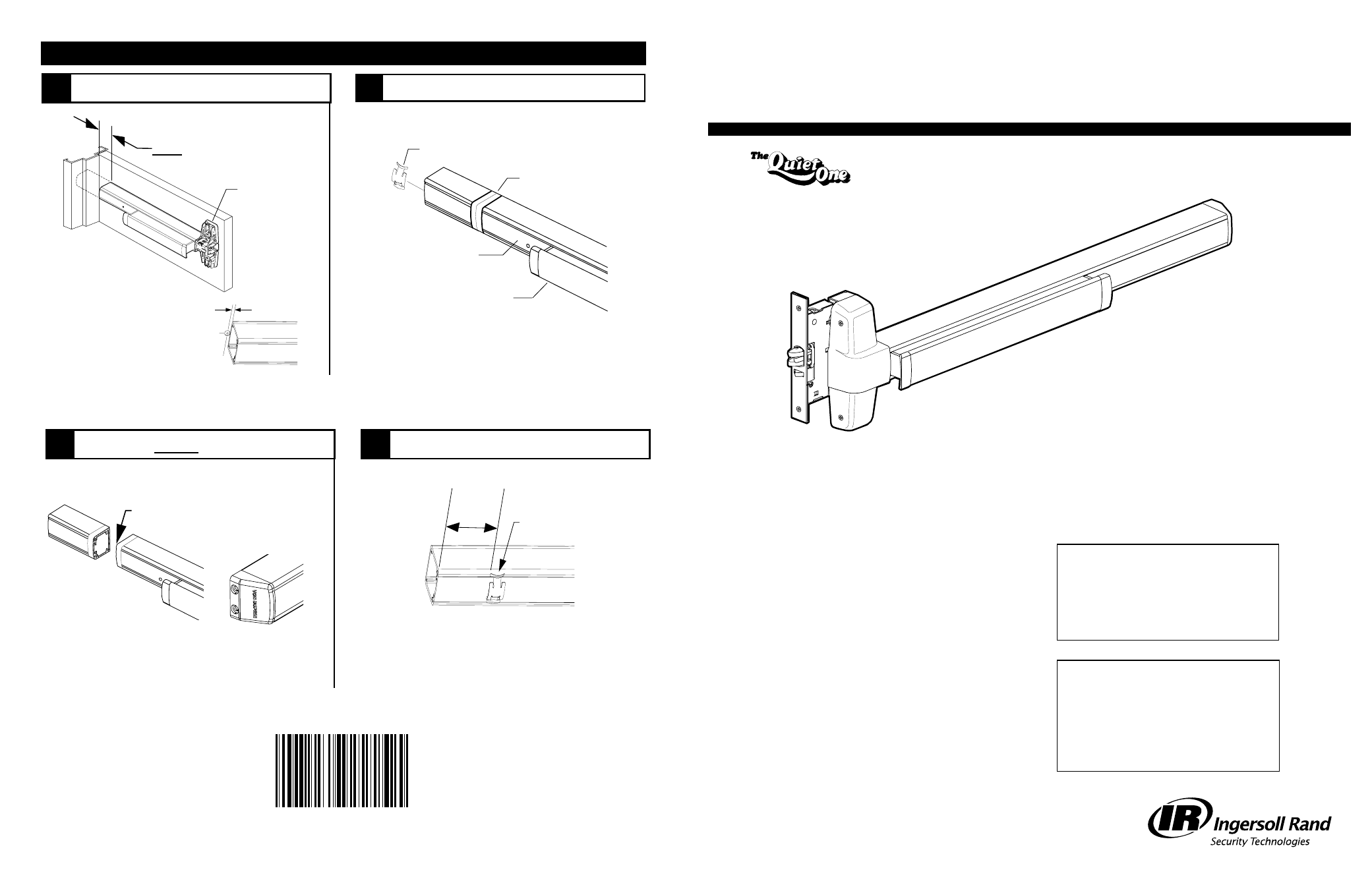
CUT DEVICE
1
Measure amount to cut off device.
8
Special tools needed:
#10-24 tap
#12-24 tap
Drill bits: #25, 1/8”, 1/4”,
5/16”, 13/32”
Index:
• Screw chart ................................... 2
• Preparation chart ......................... 3
• Device installation ................... 4-5
• Optional equipment ................ 6-7
• Cut device ..................................... 8
VON DUPRIN
®
9
2
Tape and mark area being cut.
Tape
Cover plate
(flush to pushbar)
Pushbar
Remove anti-rattle clip
If 5/8” diameter wire access hole
has been predrilled in door, cut
device 5/16” from center of hole.
Note
5/16”
Cut device square
and remove all
burrs
3
Cut device square.
NOTE: Device must
be cut square for
proper end cap fit
4
Slide anti-rattle clip into device
.
Anti-rattle
clip
2”
Minimum
1-1/2” minimum clearance
(with endcap removed)
Device aligned
with mounting
holes
Please give these instructions to building owner after device is installed