Preparation chart, 2 (double cylinder), Optional equipment – Factory Direct Hardware Von Duprin 98EO User Manual
Page 3: Cd (cylinder dogging), Cut-out for 99-2 “double cylinder” option, Figure 1 figure 2
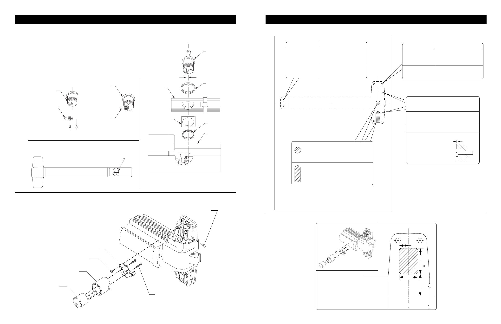
PREPARATION CHART
3
Cylinder Spacer
Rim Cylinder
Assembly
Cylinder Bracket
#8-32 X 5/16”
PPHMS
Cylinder Mounting Screws
(do not over-tighten)
#8-32 x 5/16”
PPHMS
99-2 (DOUBLE CYLINDER)
1. Remove center case cover.
2. Mount rim cylinder to cylinder bracket
as shown.
3. Mount cylinder and bracket
assembly to center case with two
#8-32 screws as shown.
6
RHR shown
(LHR opposite)
CUT-OUT FOR 99-2 “DOUBLE CYLINDER” OPTION
1-3/4”
1-3/8”
11/16”
1-1/4”
Go to instructions on next page before using preparation chart
CL
Device and strike
CL
CL
CL
X
X
OPTIONAL EQUIPMENT
1. Remove mortise cylinder cam and
reinstall in reverse (Figure 1).
2. Insert key and rotate cam to install
the cylinder to the cover plate (Figure 2).
3. Remove key to slide cover plate in
position in the mechanism case.
Std. mortise
cylinder
Mortise
cylinder
cam
Std. mortise
cylinder
Mortise
cylinder
cam
CD function conversion
Figure 1
Figure 2
Std. mortise
cylinder
Cylinder
collar
Dogging
plate cover
Offset toward
pushbar
Cylinder
locating washer
Cylinder
lock nut
Mechanism
case
Turn cylinder key clockwise approx. 1/8
turn for standard dogging
Dogging procedure
Depress pushbar
CD (CYLINDER DOGGING)
For 98-F/99-F (fire) wood door
Center case - 2 support holes
#825 Sex bolts (2) required
3/8” Drill thru
5/8” Spade drill
1/16” Deep outside
Wood or
composite
1/16”
#25 Drill #10-24 tap
1/8” Drill pilot 1” deep
Metal
W
ood
Outside cylinder applications:
Mark with template and cut-out:
Metal door (cut device side)
Wood door (cut thru)
Door cut-outs
For trim applications with working
lever, thumbpiece, or knob:
Mark with template and cut out:
(cut device side only)
Center case - 4 holes
Surface mount
Sex bolts or 990 trims
#25 Drill
#10-24 tap
1/8” Drill
pilot 1” deep
1/4” Drill (device side)
13/32” Drill (trim side)
13/32”
Drill thru
Metal
W
ood
Metal
W
ood
Surface mount
Sex bolts
#25 Drill
#10-24 tap
1/8” Drill
pilot 1” deep
1/4” Drill (device side)
13/32” Drill (trim side)
13/32”
Drill thru
Metal
W
ood
Metal
W
ood
*End cap bracket - 2 holes
*Prepare holes after lock side of device
is mounted and hinge side is leveled