Door preparation chart, Adjust rods, Frame preparation – Factory Direct Hardware Von Duprin 9947EOF User Manual
Page 3
Install bottom adjusting screw through bottom
rod (Figure 2).
With top latch bolt still retracted, adjust bottom
rod so latch bolt clears floor and bottom strike.
Turn bottom locking screw in. Do not over-tighten.
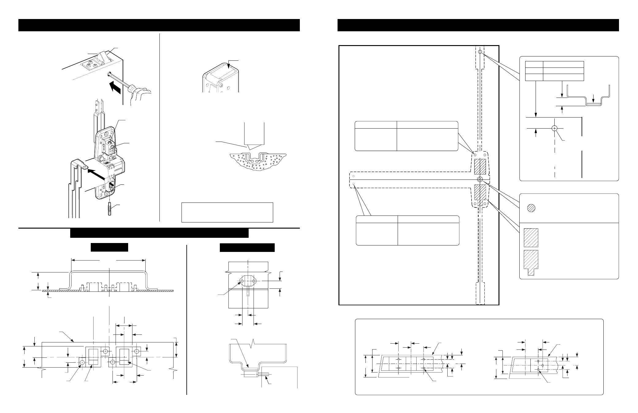
DOOR PREPARATION CHART
3
6
ADJUST RODS
FRAME PREPARATION
TOP STRIKE
RATCHET RELEASE
Latch Cases
(Drill top and bottom of door)
Ratchet Release Hole
CL
Latch
11/16” 1/2” Stop height
13/16” 5/8” Stop height
15/16” 3/4” Stop height
Drill 1/2” dia. hole
(inside face of door)
Drill & tap
#10-24
1-9/32"
7/8"
7/8"
7/16"
CL
CL
1-9/32"
1-3/4"
2-1/4"
Latch
case
Latch case and device
CL
2-1/4"
1-3/4"
1-9/32"
1-5/8"
7/8"
7/8"
7/16"
CL
Inside face
of door
Drill & tap
#10-24
Latch
case
Latch case and device
Inside face
of door
Fire Device
Panic device
Plunger must go thru
hole in door.
Adjust so plunger
releases latch bolt when
door is closed.
Reinforcing
required
Plunger
7/16”
1-1/8”
9/16”
#25 drill
#10-24 tap,
2 places
15/16”
Inside
beveled
edge
6” min.
1” min.
1/8”
Edge of stop
1-5/16”
21/32”
13/32”
15/16”
1-7/8”
Inside
beveled
edge
13/16”
13/32”
1/4” dia.
82° csk. x 3/8”
dia. in frame
Double door application
CL
CL Latch bolt
LHR door
CL
Latch bolt
RHR door
Reinforcing
required
Open door and release top
latch bolt as shown (Figure 1).
Loosen bottom locking
screw (Figure 2).
Disconnect bottom
vertical rod by removing
bottom adjusting screw.
Loosen top locking screw.
Rotate top adjusting screw
clockwise until top latch
bolt is fully extended
(Figure 1).
Check top latch
bolt for
deadlocking
(latch bolt should
not push in).
Turn top
locking screw
in. Do not
over-tighten
Depress pushbar and release.
Make sure top latch bolt stays
retracted as shown.
1.
2.
3.
4.
5.
6.
7.
8.
9.
10.
11.
12.
C
heck device operation by opening and closing door
several times from the outside.
Redo adjustment procedure if :
- Top latchbolt is not held retracted
- Bottom latchbolt does not clear
floor and bottom strike
13.
Bottom
latch bolt
(clears floor
and strike)
Figure 2
Bottom
adjusting
screw
Top
locking
screw
Top
adjusting
screw
Bottom
locking
screw
Figure 3
Figure 4
Latch case
CL
Top latch bolt
Shown fully
extended
Figure 1
Latch bolt retracted
(flush with latch case)
X
X
CL
CL
Go to instructions on next page before using preparation chart
*End cap bracket - 2 holes
*Prepare holes after lock side of device
is mounted and hinge side is equal
distance to bottom of door
Center case - 4 holes
Surface mount
Sex bolts or 990 trims
#25 Drill
#10-24 tap
1/4” Drill (device side)
13/32” Drill (trim side)
Door Cut-outs
For all 98/9947 and
98/9947-F devices:
Trace cut-outs from
plastic template
(cut device side only)
Outside cylinder applications:
Mark with template and cut-out:
Metal door (cut device side)
Wood door (cut thru)
1-5/8”
Surface mount
Sex bolts or 990 trims
#25 Drill
#10-24 tap
1/4” Drill (device side)
13/32” Drill (trim side)