Dexter Laundry T-120 (On-Premise) User Manual
Page 7
- 7 -
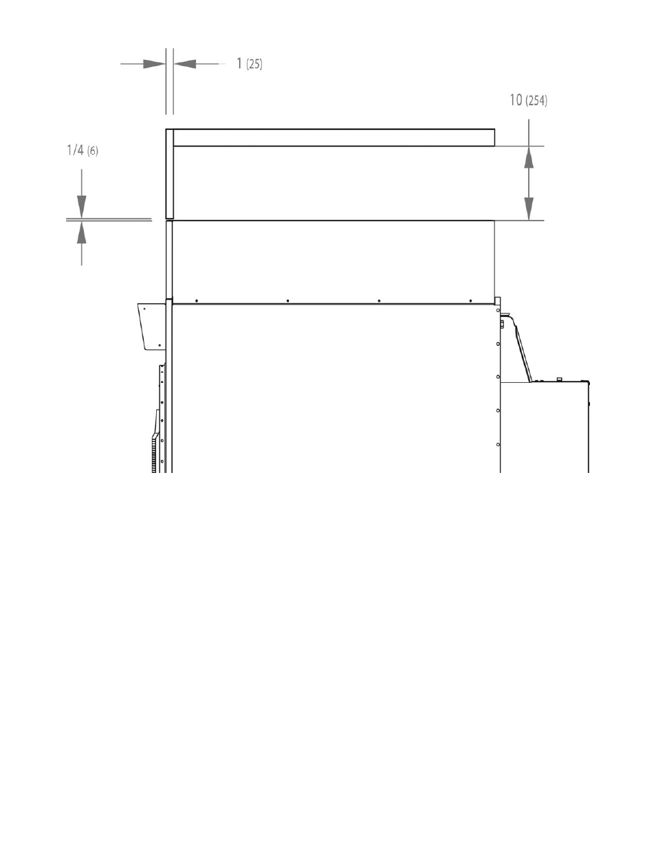
VERTICAL CLEARANCE DIMENSIONS
3. MAKE-UP AIR. Adequate make-up air (
1250
CFM (35.4 m³/minute) for 60 Hz machines with 10” exhaust,
1450 CFM (41 m³/minute) for 60 Hz machines with 12” exhaust,
1000
CFM (28.3 m³/minute) for 50 Hz machines
with 10”/12” exhaust) must be supplied to replace air exhausted by dryers on all types of installations. Provide a
minimum of 2.25 ft² (0.2 m²) make-up air opening to the outside for each dryer. This is a net requirement of
effective area. Screens, grills or louvers, which will restrict the flow of air, must be considered. Consult the supplier
to determine the free area equivalent for the grill being used.
The source of make-up air should be located sufficiently away from the dryers to allow an even airflow to the air
intakes of all dryers. Multiple openings should be provided.
NOTE: The following considerations must be observed for gas dryer installations where dry cleaners are
installed. The sources of all make-up air and room ventilation air movement to all dryers must be located
away from any dry cleaners. This is necessary so that solvent vapors will not be drawn into the dryer
inlet ducts. Dry cleaner solvent vapors will decompose in contact with an open flame such as the gas
flame present in clothes dryers. The decomposition products are highly corrosive and will cause damage
to the dryer(s), ducts and clothes loads.
4.
ELECTRICAL REQUIREMENTS. The electrical power requirements necessary to operate the unit satisfactorily
are listed on the serial plate located on the back panel of each dryer. The electrical connection should be made to
the
terminal block in the rear control box assembly
on the rear of the unit, using a wire size adequate to handle the
amperage and voltage listed on the serial plate, but never smaller than No.12 AWG wire. It is absolutely necessary
that the dryer be grounded to a known ground.
Individual circuit breakers for each unit are recommended. The wiring diagram is located on the belt guard on
the back of the machine.