Fk g a, Fig. 6 connection of 3b net log – 3B Scientific Teltron Critical Potentials Tube S with He-Filling User Manual
Page 6
6
•
Set the control unit to ramp mode and con-
figure a minimum voltage of about 10 V, with
a maximum voltage of about 35 V.
•
Select a heater voltage of some 3.5 V and a
collector voltage of around -1.5 V.
Oscilloscope settings:
Channel 1: 50 mV/div
Channel 2: 0.2 V/div
Time-base: 5 ms
Trigger on Channel 1
•
Vary the heating voltage, the upper and lower
limits of the accelerating voltage and the os-
cilloscope parameters until the best curve can
be seen.
•
In order to display the ionisation curve, re-
verse the polarity of the collector voltage.
BETRIEBSGERÄT FRANCK-HERTZ/OPERATING UNIT FRANCK-HERTZ
F
K
G
A
Heizung
Filament
Gitter/Grid
Beschleunigung/Acceleration
Reverse bias
E
V
Man/Ramp
+/-
1
10
U
U
x
A
= +
1
10
U
I
V
Y
E
= *
U
F
V
U
G
V
U
Amin
V
U
Amax
V
0
0
0
80
80
12
U
E
V
0
12
+
I
in
A
U
out
A
U
in
A
+
U
out
B
U
in
B
+
Channel
Rate
Store
Date/Time
On/Off
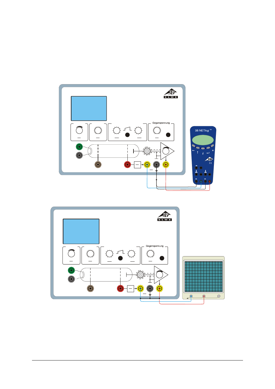
Fig. 6 Connection of 3B NETlog
TM
to the control unit for the Franck-Hertz experiment
BETRIEBSGERÄT FRANCK-HERTZ/OPERATING UNIT FRANCK-HERTZ
F
K
G
A
Heizung
Filament
Gitter/Grid
Beschleunigung/Acceleration
Reverse bias
E
V
Man/Ramp
+/-
1
10
U
U
x
A
= +
1
10
U
I
V
Y
E
= *
U
F
V
U
G
V
U
Amin
V
U
Amax
V
0
0
0
80
80
12
U
E
V
0
12
EXT
CH1
(X)
CH2
(Y)
OSCILLOSCOPE
Fig. 7 Connection of oscilloscope to the control unit for the Franck-Hertz experiment