1 procedure with 3b net log, Connect the 3b net log, Unit and output uy to input b – 3B Scientific Teltron Critical Potentials Tube S with He-Filling User Manual
Page 5: Set up the 3b net log, Interface, the 3b net lab
5
HERTZ TUBE CONSOLE
60
V
A
+
1
RING
2
SLOW
RUN
MIN
MAX
V
A
SET
3
4
1 SLOW 2
1
2
FAST
0...±1 VOLT OUT
0...±1 VOLT OUT
OUT
3
4
200 mV
!
EXT
CH1
(X)
CH2
(Y)
OSCILLOSCOPE
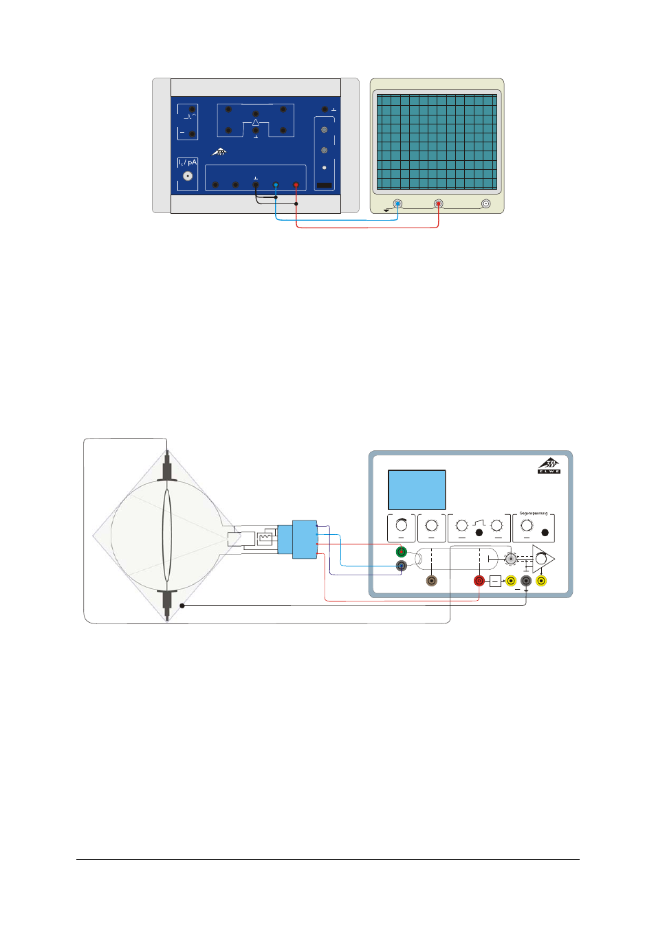
Fig. 4 Connection of an oscilloscope to the control unit for critical potential tubes
7.3 Experiment set-up with the control unit
for the Franck-Hertz experiment
•
Insert the tube into the tube holder.
Provision of heater voltage V
F
:
•
Connect socket F3 on the tube holder to
socket F on the control unit for the Franck-
Hertz experiment and connect socket F4 to
socket K. (refer to Fig. 5)
Provision of accelerating voltage V
A
:
•
Connect socket C5 on the tube holder to
socket K on the control unit and socket A1 to
socket A.
The provision of collector voltage V
R
is handled
internally inside the control unit for the Franck-
Hertz experiment.
•
Put the shielding over the tube and slot it into
the groove on the tube holder so that the tube
is completely enclosed by shielding. Then
connect the control unit by means of the
ground socket.
•
Connect the collector ring to the BNC input
on the control unit.
A1
F3
F4
C5
BETRIEBSGERÄT FRANCK-HERTZ/OPERATING UNIT FRANCK-HERTZ
F
K
G
A
Heizung
Filament
Gitter/Grid
Beschleunigung/Acceleration
Reverse bias
E
V
Man/Ramp
+/-
1
10
U
U
x
A
= +
1
10
U
I
V
Y
E
= *
U
F
V
U
G
V
U
Amin
V
U
Amax
V
0
0
0
80
80
12
U
E
V
0
12
Fig. 5 Experiment set-up with the control unit for the Franck-Hertz experiment
7.3.1
Procedure with 3B NETlog
TM
•
Connect the 3B NETlog
TM
unit to the control
unit for the Franck-Hertz experiment (see
Fig. 6). Connect the Ux output of the control
unit to input A of the 3B NETlog
TM
unit and
output Uy to input B.
•
Set the control unit to ramp mode and con-
figure a minimum voltage of about 10 V, with
a maximum voltage of about 35 V.
•
Select a heater voltage of some 3.5 V and a
collector voltage of around -1.5 V.
•
Set up the 3B
NETlog
TM
interface, the
3B NETlab
TM
computer program and the
measurement recording as described in sec-
tion 7.2.1.
•
Vary the heating voltage, the upper and lower
limits of the accelerating voltage and the gain
until the best optimal can be seen.
•
In order to display the ionisation curve, re-
verse the polarity of the collector voltage.
7.3.2
Procedure with an oscilloscope
•
Connect the Ux output of the control unit to
Channel 1 (X deflection) of the oscilloscope
and output Uy to Channel 2 (Y deflection)
(see Fig. 7).