1 rear panel connections, 2 front panel controls, Getting started – dbx 1074 User Manual
Page 10: Iec power cord receptacle, Power switch, Output connectors, Operating level switch, Key input jack, Input connectors, Filter control - 80hz to 8khz
1074
1074 User Manual
6
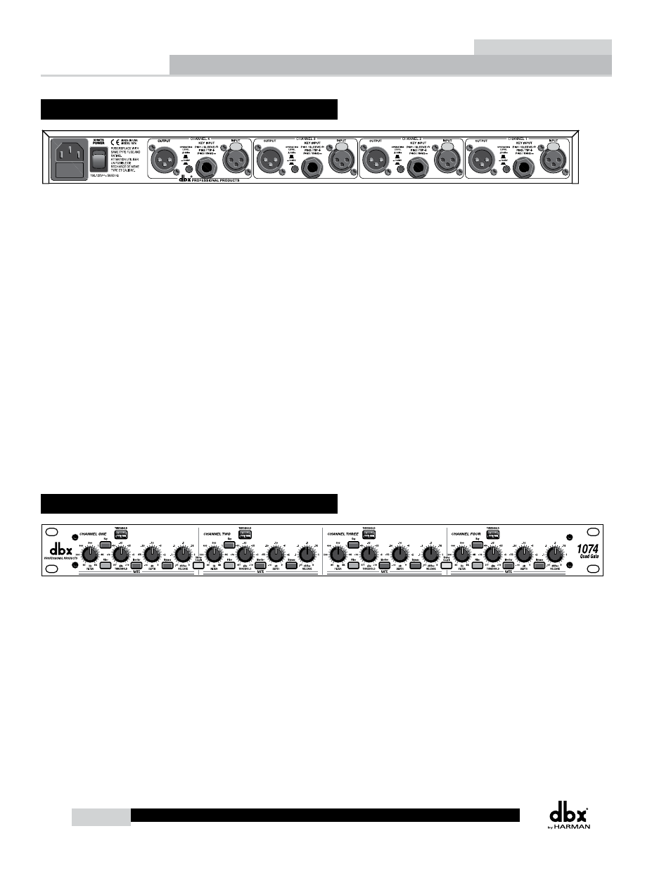
1.1 Rear Panel Connections
NOTE:
Paint:
Ink:
(1) Urethane Black
(1) Opaque White
dbx 1074
Chassis Rear Artwork
85-0432-C
12.09.05
31028
DESCRIPTION:
ECN:
P/N:
DATE:
FUSE: T 300mA L 250V
IEC Power Cord Receptacle
This is the power cord receptacle of the 1074. An IEC cord is included with the shipped product.
Power Switch
Turns the 1074 on and off.
Output Connectors
The output section of the 1074 offers electronically balanced XLR connections. An output transformer
option is available when very long cable distances are required (see “Specifications”).
Operating Level Switch
The Operating Level switch allows you to select between either a +4dBu operating level or -10dBv
operating level, allowing you to match the operating level of the connecting components.
Key Input Jack
The 1/4” TRS Key Input jack, allows you to add a source signal directly into the gating path of the
1074, which is used to trigger the gating effect.
Input Connectors
The input section of the 1074 offers electronically balanced XLR connections.
1.2 Front Panel Controls
Note:
The following controls are independently adjustable for each channel
of the 1074 or can be stereo coupled per pair of channels – the
exception, of course, being the STEREO COUPLE switch.
Filter Control - 80Hz to 8kHz
The Filter control allows you to select the frequency at which gating
occurs. Frequency ranges from 80Hz to 8kHz.
Filter - On/Off
Pressing the Filter switch will engage the filter.
Key Input - On/Off
Pressing the Key switch will engage the inserted Key input source signal.
Getting Started
Section 1