User guide – dbx ZC-BOB User Manual
Page 4
®
DriveRack
®
/ZonePRO
™
User Manual
4
ZC-Remote Control Wall Controllers
USER GUIDE
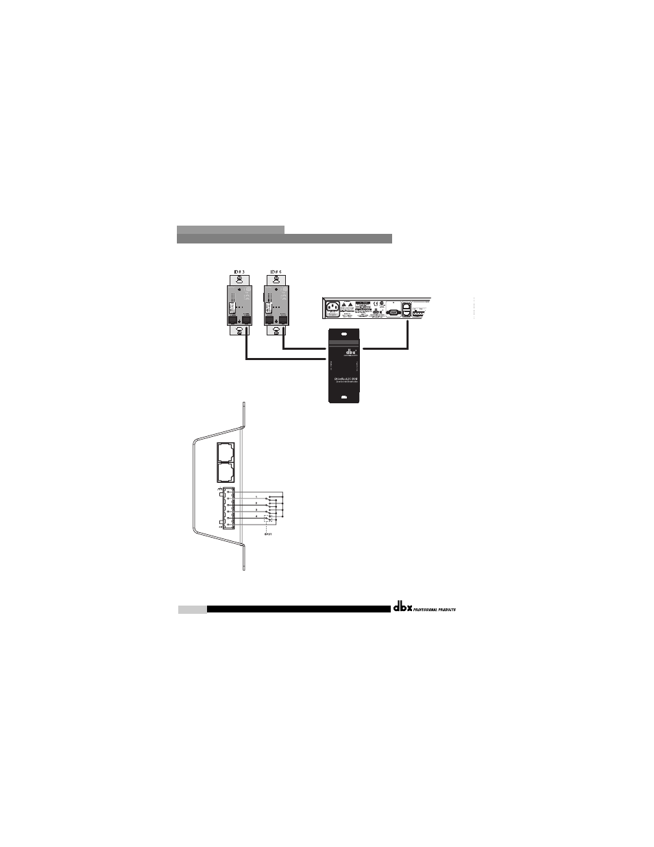
Diagram C
Diagram D
ZC-4
ZC-4 Binary App notes
SW4
SW3
SW2
SW1
Hex
Setting
0
0
0
0
0
0
0
0
0
1
1
1
0
0
1
0
2
2
0
0
1
1
3
3
0
1
0
0
4
4
0
1
0
1
5
5
0
1
1
0
6
6
0
1
1
1
7
7
1
0
0
0
8
8
1
0
0
1
9
9
1
0
1
0
A
10
1
0
1
1
B
11
1
1
0
0
C
12
1
1
0
1
D
13
1
1
1
0
E
14
1
1
1
1
F
15
Switches SW1-SW4 correspond to switch inputs 1-4 on the ZC4's
EuroBlock connector.Each switch connected to the ZC4 must be a
Dual Pole Single Throw (DPST). One pole of each switch should
be connected to the ground reference on the ZC4's EuroBlock con-
nector while the other pole should be connected to the +V refer-
ence. Because there are four switch inputs, there are 16 possible
switch combinations. In the chart above, a "0" cooresponds to a
switch connected to +V reference, while a "1" cooresponds to the
switch being connected to ground. None of the poles should be
left hanging but should either be connected to +V or ground.
- AFS224 Manual (24 pages)
- 1066 (24 pages)
- 1046 (48 pages)
- 1046 (16 pages)
- db12 (2 pages)
- ZonePRO App Guide (4 pages)
- TR1616 (32 pages)
- DriveRack PA2 Complete Loudspeaker Management System (70 pages)
- DriveRack PA2 Quickstart Guide (2 pages)
- 231s Equalizer (12 pages)
- PS6 (2 pages)
- ZonePRO 1260 (1 page)
- 234s Crossover (20 pages)
- 166xs (28 pages)
- PB48 (4 pages)
- DriveRack 220i (57 pages)
- DriveRack 260 (84 pages)
- DriveRack 4820 (96 pages)
- 376 (37 pages)
- iEQ15 (20 pages)
- ZC controller connectivity and association (1 page)
- Advanced Feedback Suppression AFS224 (11 pages)
- 162SL (31 pages)
- 266xs - Compressor/Gate (16 pages)
- ZonePRO 641m Digital Zone Processor (60 pages)
- DriveRack PX Quickstart Guide (24 pages)
- 1074 (16 pages)
- PX (48 pages)
- 2031 Equalizer (40 pages)
- 1231 Equalizer (44 pages)
- 286s (28 pages)
- 386 (35 pages)
- 160SWP (8 pages)
- 160SL (32 pages)
- 120A (16 pages)
- db10 (2 pages)
- DriveRack PA+ Quickstart Guide (16 pages)
- ZonePRO 641m (1 page)
- 160A (20 pages)
- PMC16 (64 pages)
- DriveRack PA+ (40 pages)
- DriveRack VENU360 Loudspeaker Management System (127 pages)