Heat sink specifications, Th ermal resis tan ce (d eg c/w ) – Ironwood Electronics SG-BGA User Manual User Manual
Page 15
P a g e | 1 5
S G B . d o c , R e v . R , V P , 1 1 / 5 / 1 0
Tel: (800) 404-0204
www.ironwoodelectronics.com
Vibration
Standard:
MIL-STD202, METHOD 204, CONDITION A
No change in resistance and thickness
Humidity
Standard:
MIL-STD202, METHOD 106
Resistance change: 26 m
Thickness change: -1%
Standard:
MIL-STD202, METHOD 103, CONDITION A
Resistance change: 15 m
Thickness change: -6%
Thermal Shock
Standard:
MIL-STD202, METHOD 107, CONDITION A
Resistance change: -19 m
Thickness change: -1%
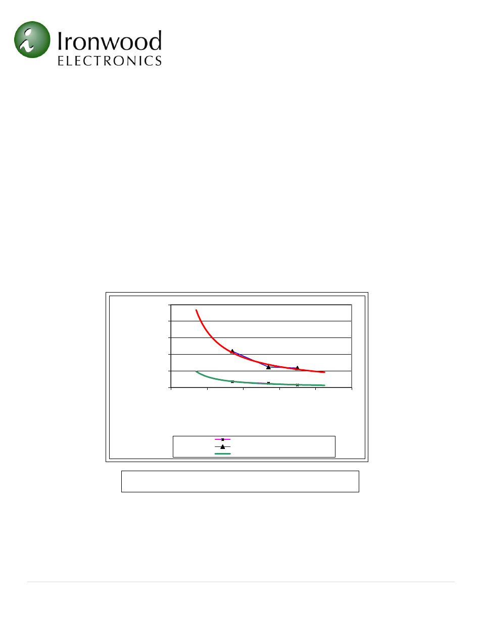
Heat Sink Specifications
The graph (Figure 15) shows thermal resistance of the socket as well as socket with a fan (Papst 3412/9 GL,
35.9 CFM, 6” muffin) blowing directly on it. For high power dissipation, a specific heat sink lid can be
designed using QFIN software. Please call Ironwood Tech Support @1-800-404-0204.
0
10
20
30
40
50
0
10
20
30
40
50
Th
ermal
resis
tan
ce
(d
eg
C/W
)
IC Size (mm)
Socket+Fan
Socket Only
Trend (Socket+Fan)
Figure 15: Heat Sink Characteristics