C and preferably <10 – Ironwood Electronics SG-BGA User Manual User Manual
Page 11
P a g e | 1 1
S G B . d o c , R e v . R , V P , 1 1 / 5 / 1 0
Tel: (800) 404-0204
www.ironwoodelectronics.com
recommends contacting your solder paste / flux manufacturer for proper reflow profiles for your particular set-
up and equipment.
Recommended Reflow Profile – Low Temperature (Non-RoHS)
Ironwood's SMT adaptor closely emulates a BGA package and therefore can employ similar processes to attach
it to a target board. The steps involved in the soldering process are as follows:
(1) Using a flux dispenser, place a small amount of flux (water soluble or no clean) on the middle of the target
PCB lands. Spread the flux evenly over the PCB lands.
(2) Apply a small amount of TAC flux on opposite corners of the PCB lands.
(3) Note the target board land pattern orientation and the SM adaptor Pin 1 location. Place the adaptor (solder
ball side down) onto the flux and land pattern (align as closely as possible to the land pattern of the target PCB).
The SM adaptors are durable enough to
be handled by hand, however vacuum pen
or pick & place equipment can be used
for handling the part.
(4) Surface tension between the adaptor's
solder spheres and the target PCB's pads
will self-align the part during the reflow
process.
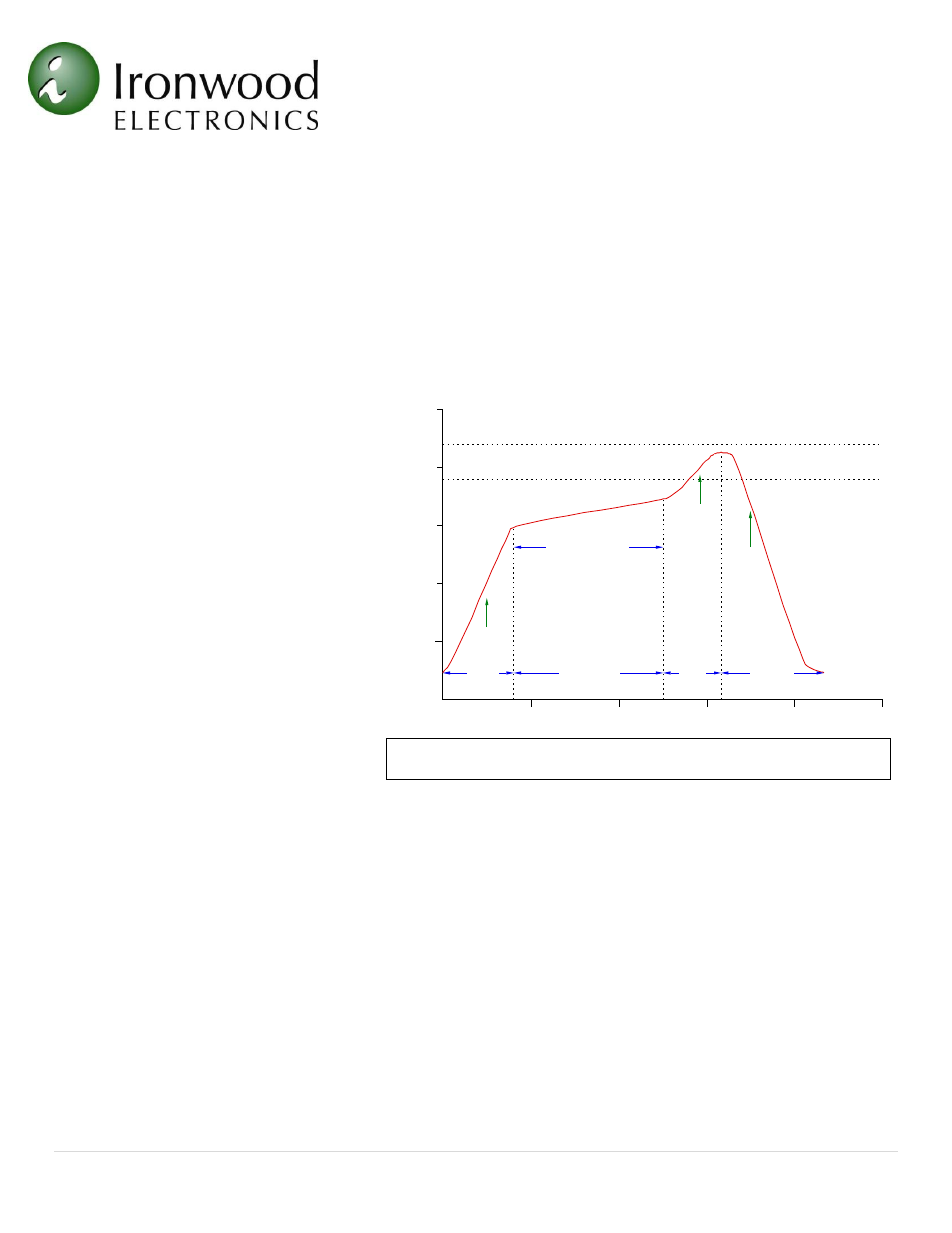
(5) Reflow as per (Figure 11):
Use caution when profiling to insure
minimal
temperature
difference
(<15
0
C and preferably <10
0
C)
between components
Forced
convection
reflow
with
nitrogen preferred (50 - 75 PPM)
Preheat stage temperature ramp rate:
<2
0
C per second
Time required in Flux Activation
stage: 150 to 180 seconds
Flux Activation stage temperature range: 150 to 183
0
C
Time required in Solder stage: 60 seconds
Maximum temperature 210 - 220
0
C (Do not exceed 10 seconds at maximum temperature)
Cool-Down stage temperature reduction rate: <20 C/sec
NOTE: It may be necessary to adjust the amount of heat when attaching the part, due to the fact that the adaptor
mass is different from the actual IC package. Solder sphere spec = 63Sn, 37Pb and its melting point = 183 C
(6) Clean PCB with the flux manufacturers recommended process after reflow. Install the GHz socket on the
SM adaptor as per assembly instruction provided in the GHz socket assembly section.
250
200
150
100
50
0
100
200
300
400
500
Preheat
Flux Activation
Reflow
Cool-Down
<2°C
per Second
150 - 180 Seconds
<2°C
per Second
1° to 3°C
per Second
Time (seconds)
T
em
p
er
at
u
re
(°
C
)
Maximum Package Body Temperature
Solder Temperature Melting Point
Figure 11: Recommended Reflow Profile – non RoHS
Figure 4: Example Insulation Plate