3 fault codes, troubleshooting – R&M Materials Handling VARIABLE SPEED CONTROLS CMXC 007 Service Manual User Manual
Page 7
R&M Materials Handling, Inc.
4501 Gateway Boulevard
Springfield, Ohio 45502
P.: (937) 328-5100
FAX: (937) 325-5319
7/9
R&M Materials Handling, Inc. reserves the right to alter or amend the above information without notice.
3 FAULT CODES, TROUBLESHOOTING
There are high voltages inside the inverter (including the programming switches).
Wait for at least three minutes after the supply voltage has been switched off before
any service actions.
When the inverter detects a fault situation it stops running and starts signalling the fault code by blinking the
indication leds (green and red). The blinking of the code is carried on until a new fault occurs or until power is
switched off. The fault codes are explained in the table below.
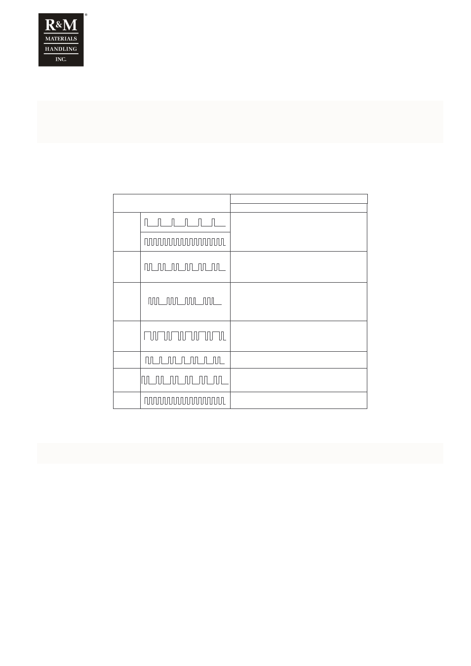
Fault code, color
Fault. Possible cause. Checkings.
DMCS007
GREEN
Overvoltage. Mains voltage is too high or ramp
time is too short. Check the voltage of all supply
phases at the terminal X1. If they are ok then
set a longer ramp by switch S3.
GREEN
Stall supervision / overcurrent. Brake does
not open properly or there is an obstackle on
the track. Check also that the setting of switch
S4 is made according to the supplied motor(s).
GREEN
Deceleration ramp supervision. Deceleration
ramp has not been followed. If the fault occurs
again set longer ramp time by switch S3. Check
also the voltage of all supply phases at the
terminal X1.
GREEN
Inverter overtemperature. Motor current is too
high (bearing problem, obstacle on the track,
brake does not open properly,…) or the
ambient temperature is too high.
GREEN
Undervoltage. Check the voltage of all supply
phases at the terminal X1.
RED
Short circuit. Switch the power off. Check the
insulation of the motor cables and the motor
windings.
RED
Microprocessor fault. Switch the power off for
10 seconds. Then power-up the inverter.
The latest active fault is removed from the memory always when power is switched off.
If inverter is not in a fault state, but driving is not possible:
Motor will not start if dc-bus voltage too high (above 745V), this occurs if any of line-to-line voltages exceeds
480V+5% = 508V
o
If line voltage cannot be reduced, install drop-down transformer
Check the supply voltage phases at terminal X1.
Check the control signals at terminal X1.
Check that the control voltage level is correct. Rating plate is located on the left side of the inverter.
Check all parameters, especially the motor parameters (switch S4).
Check that the motor(s) corresponds the selected motor parameters.
Check that the microprocessor starts running. Both indication leds (green and red) blink once as the inverter is
powered up. After the one second initialising-time only the green led should be light.
Check that the brake opens and closes properly. Check the brake airgap if necessary.