3 normal operation, 4 status indication leds (green and red), 5 compact brake motors – R&M Materials Handling VARIABLE SPEED CONTROLS CMXC 007 Service Manual User Manual
Page 4: 6 programming switches
R&M Materials Handling, Inc.
4501 Gateway Boulevard
Springfield, Ohio 45502
P.: (937) 328-5100
FAX: (937) 325-5319
4/9
R&M Materials Handling, Inc. reserves the right to alter or amend the above information without notice.
Technical data
DMCS007
Humidity
95% N.C. (without dripping)
Degree of protection
Frequency converter + cover (IP20)
Dimensions (WxHxD)
133x92x60mm
Altitude
Output current must be reduced 1 % for every 100 m over 1000 m. For altitudes over 3000
m, manufacturer must be consulted.
Pollution degree
Pollution degree 2 according to NEMA ICS-1, IEC664 and UL840
Vibration
IEC68-2-6
Shock
IEC68-2-27
1.3
Normal operation
The inverter goes into the ready-to-run state within one second after the power supply is connected. During running
the inverter follows the operator’s speed reference according to the set acceleration/deceleration ramp. During
direction change the brake is kept open all the time. When drive command is switched off the inverter decelerates
to zero according to the set ramp and closes the mechanical brake.
1.4
Status indication leds (green and red)
The inverter indicates its operating state by two leds. Red led indicates “fault state” (driving is inhibited). Green led
indicates “ok-state”. Blinking of green led indicates that fault state has been active, but it has been recovered.
Normal driving is however possible also when green led is blinking (in other words, blinking of green led does not
indicate “warning-state”).
1.5
Compact brake motors
This inverter is used with Compact brake motors, which have been especially designed for this use. The Compact
brake motors have the following special features:
Compact brake, which is opened by the magnetic force of the motor. When the magnetic force is removed (by
cutting off the motor current) the brake is closed by spring force.
High nominal frequency (80Hz…120Hz)
1.6
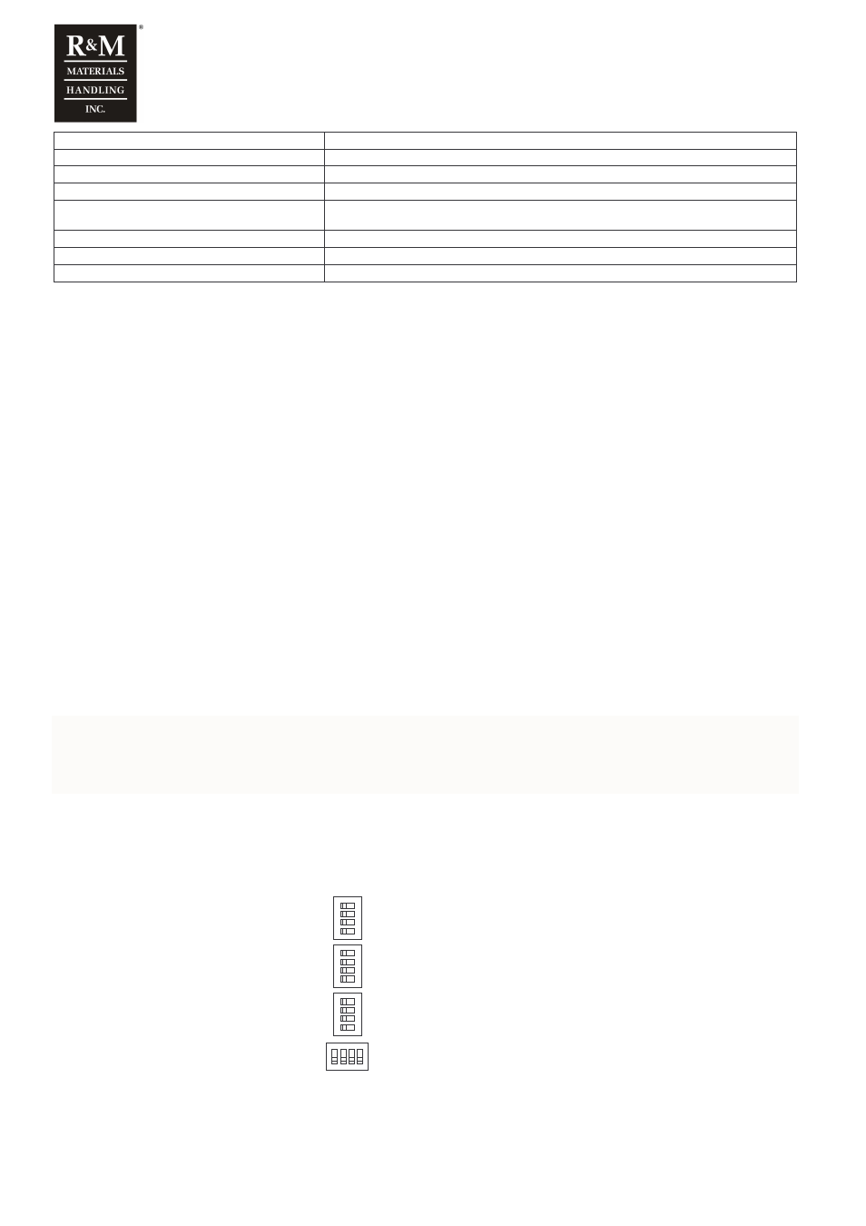
Programming switches
WARNING!!! There are high voltages inside the inverter (including the programming
switches). Wait for at least three minutes after the supply voltage has been switched
off before any service actions.
The programming of the inverter is performed by dip-switches. The state of each switch is either OFF (0) or ON (1).
There are five parameters that are possible to set by the switches S1-S4.
DMSC007
O
N
D
IP
1
2
3
4
O
N
D
IP
1
2
3
4
O
N
D
IP
1
2
3
4
ON
DIP
1 2 3 4
S1
S2
S3
S4
S1 = Maximum speed
S2 = Minimimum speed
S3 = Acceleration / deceleration time
S4 = Control mode and motor type