Measurement operation, 1 dc & ac voltage measurement, 2. resistance measurement – Prokit's Industries MT-1910 User Manual
Page 5: 3. diode/continuity check
6
7
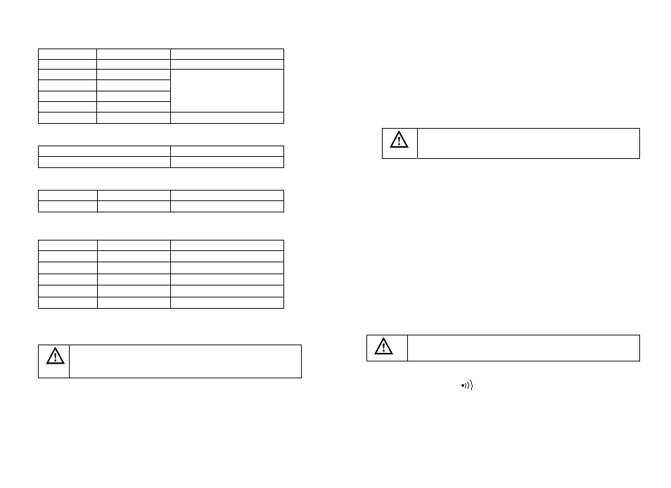
4.2.9 Capacitance
Range
Resolution
Accuracy
2nF 0.001nF
20nF 0.01nF
200nF 0.1nF
(
4.0%rdg +5dgt)
2µF 0.001µF
20uF 0.01µF
200µF 0.1µF
(
5.0%rdg + 10dgt)
* Over load protection:use the fuse[F250mA/1KV]
4.2.10 hFE
Range
Function
hFE
hFE: 1~1000
* Over load protection:use the fuse [F250mA/1KV ]
4.2.11 Frequency
Range
Resolution
Accuracy
20kHz 1
Hz
±(1.5%rdg+5dgt)
* Sensitivity: 200mV -5V AC rms
* Over load protection:250V DC/AC rms
4.2.12 Inductance
Range
Resolution
Accuracy
2mH 0.001mH (4.0% rdg + 8dgt)
20mH 0.01mH
(
4.0%rdg + 3dgt)
200mH 0.1mH
(
4.0%rdg + 3dgt)
2H 1mH
(
4.0%rdg + 3dgt)
20H 10mH
(
4.0%rdg + 5dgt)
* Over load protection:use the fuse [ F250mA/1KV]
5. Measurement operation
5-1 DC & AC voltage measurement
To avoid harms to you or damage to the meter from electric
shock. Please do not attempt to measure voltage higher than
DC 1000V/AC 700Vrms although readings may be obtained.
The DC voltage ranges are 200.0mV, 2.000V, 20.00V, 200.0V and 1000V.
The AC voltage ranges are 200.0mV, 2.000V, 20.00V, 200.0V and 750.0V.
To measure DC/AC voltage:
1. Insert the red test lead into the “VΩ” input terminal and the black test lead
into the COM terminal.
2. First, default mode is DC measurement mode, you can select the AC voltage
mode by press ‘FUNC“ key.
3. Set the rotary switch to proper DC/AC mV or V range.
4. Connecting the test lead across with the object be measured. The measured
value will be showed on the LCD display.
6. If the “OL” symbol is displayed on the LCD, please set the rotary switch to
the higher range.
Note:
In the range of 200mV in DC/AC and 2V AC, even in the absence of input or
connectivity test lead, there also have something display on LCD. In this case,
short-circuit "V" and "COM", the LCD display will back to zero.
5-2. Resistance measurement
To avoid damage to the Meter or to the equipment under
test, disconnect power and discharge all high-voltage
capacitors before resistance measurement.
The resistance range: 200Ω, 2.000kΩ, 20.00kΩΩ, 200.0k, 2.000MΩ, 20.00MΩ
To measure resistance, connect the meter as follows:
1.
Insert the red test lead into the ”VΩ” terminal and the black test lead into the
COM terminal.
2.
Set the rotary switch to proper resistance range.
3.
Connect the test lead across with the object be measured. The measured value
will be display on the LCD
Note:
The test lead can add 0.1Ω to 0.2Ω of error to resistance measurement. To obtain
precision reading in low-resistance measurement, that is the range of 200.0Ω,
short the input terminal before measuring. Then the contact resistance will be
displayed on the LCD. You can subtract the contact resistance value from the
measured value.
z
For high-resistance measurement (>10MΩ), it is normal taking several
second to obtain stable reading.
z
The LCD display “OL” indicating open-circuit for the tested resistor or the
resistor value is higher than the maximum range of the meter.
5-3. Diode/Continuity check
To avoid damage to the Meter or to the equipment under
test, disconnect power and discharge all high-voltage
capacitors before Diode/Continuity check.
1. Insert the red test lead into the “VΩ” terminal and the black test lead into the
COM terminal.
2. Set the rotary switch to
Ω position.
3. For forward voltage drop reading on any semiconductor component, place the
red test lead on the component anode and place the black test lead on the
component cathode. The measured value show on the LCD.
4. Select the continuity check mode by the “FUNC” key.
The buzzer may be sound if the resistance of a circuit under test is less than
30Ω.