MAX Power VIP250-HYD User Manual
Page 6
VIP 250, Hydraulic with Electronic Controller
25/12/2005
6
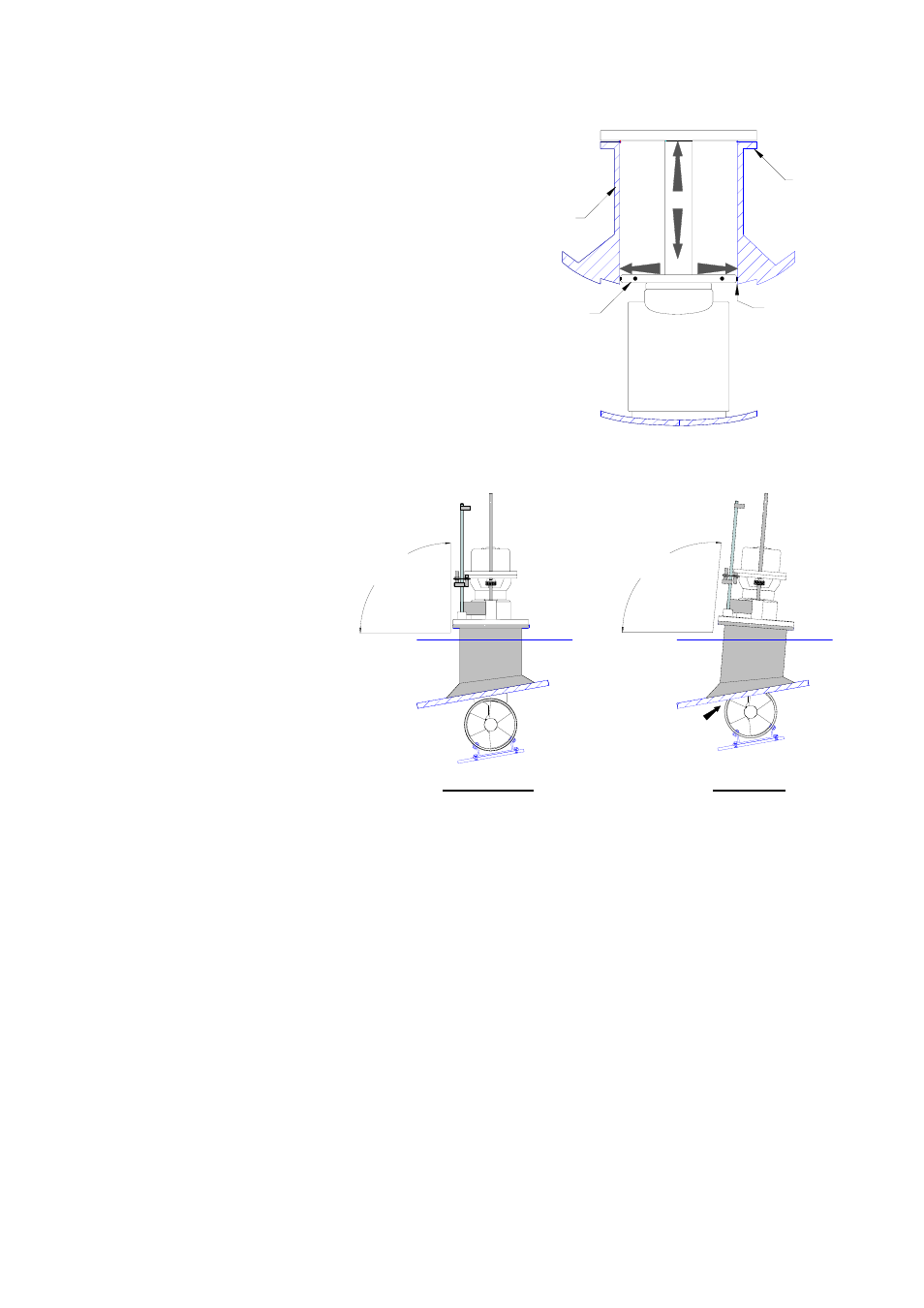
( a )
( b )
< 2 mm
Thrust Plate
Mounting
Base
Mounting
Base
Flange
90°
CORRECT
Water
Line
Water
Line
Not 90°
WRONG
Before fixing the thruster unit onto the mounting base flange it is important to ensure
that the top surface of the mounting base flange is perfectly flat in order to accept the
« O » ring seal of the VIP base flange in order to ensure perfect water tightness.
The bolts fixing the VIP onto the mounting flange must be inserted from top to bottom.
Provide sufficient access underneath the flange to allow for tightening the nuts. If the
access is not possible, provide a special mounting flange with metric studs or tapped
holes.
The VIP pushes its thrust plate sideways
against the inside of the mounting base
when running. This means that one must
totally lower the unit and check the
following:
(a)
That the VIP’s thrust plate is free to
move up and down.
(b)
And also that there is no more than
2mm horizontal movement
between the thrust plate and the
mounting base, especially when
fully down.
The mounting base
flange should be parallel
to the waterline.
In other words the
thruster unit must be
installed vertical with its
turbine totally clear of
the hull in the down
position.