MAX Power VIP250-HYD User Manual
Page 24
VIP 250, Hydraulic with Electronic Controller
25/12/2005
24
9.5 WIRING LOOM OF MOTOR/RELAY UNIT:
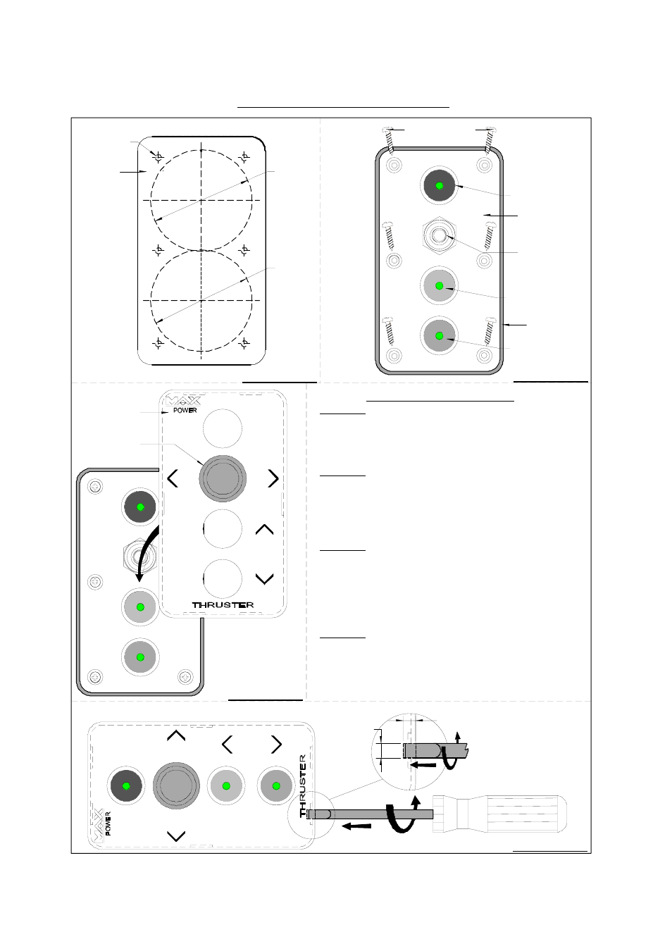
Control Panel Installation Guidelines:
DIAGRAM: 1
DIAGRAM: 2
DIAGRAM: 3
DIAGRAM: 4
Fixing Screws
Clip-on Cover
Base Unit
Rubber Seal
Ø52 mm
(2 in.)
Ø52 mm
(2 in.)
Drilling
Template
RED Push-button
with Green LED.
Ø1 mm
INSTALLATION GUIDELINES
Diagram: 1
1.1) Stick drilling template in desired mounting position.
1.2) Drill the two 52 mm diameter holes using a holesaw.
1.3) Place panel in holes and mark the 6 fixing holes.
1.4) Remove panel and drill the six 1 mm diameter fixing holes.
Diagram: 2
2.1) Make sure that rubber seal is placed on the base column.
2.2) Wire and/or plug unit to the control circuit.
2.3) Position base so that the joystick is to the top and the
"Red" button to the bottom.
2.4) Fix base unit with the six fixing screws as supplied with unit.
Diagram: 3
3.1) Only when totally finished and satisfied with wiring and
positioning of the unit, clip-on the face panel/cover.
3.2) Leave rubber joystick cover inserted to clip-on cover
when clipping cover into place and push down well
once in place.
Diagram: 4
4.1) To remove the clip-on cover slide a flat headed screwdriver,
with 6 - 7 mm wide tip, between the clip-on cover and the
dashboard at position (a), (b) and then (c) and twist the tip
slightly. Push in the tip of the screwdriver at least 3 to 4 mm
before twisting it.
(b)
(a)
(c)
Push & Twist
Push & Twist
6 to 7 mm
3 to 4 mm
GREEN Push-button
with Green LED
BLACK Push-button
with Green LED
Joystick
Rubber
Joystick
Cover