Peerless-AV HDS-IWK-200 - Installation User Manual
Page 9
9 of 24
ISSUED: 08-23-12 SHEET #: 180-9027-2 10-30-12
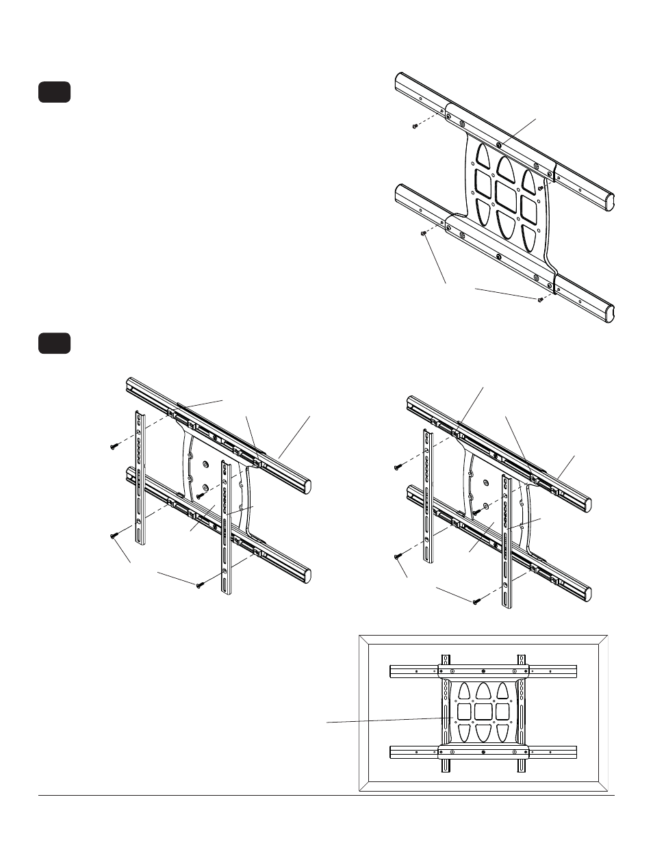
Remove four 1/4-20 self tapping screws to detach display brackets from outer mount holes of universal adapter
bracket using a 5 mm allen wrench as shown in fi gure 1.5. Reinstall four 1/4-20 self tapping screws to secure
display brackets to inner set of mounting holes on universal adapter bracket as shown in fi gure 1.6.
Remove four 1/4-20 x .6" screws using a 5 mm allen wrench
and loosen two 1/4-20 x 1.25" screws 1/2 turn to allow for
display bracket adjustment.
1/4-20 SELF
TAPPING SCREWS
1/4-20 SELF
TAPPING SCREWS
DISPLAY
BRACKETS
DISPLAY
BRACKETS
INNER
MOUNTING
HOLES
OUTER
MOUNTING
HOLES
fi g. 1.5
fi g. 1.6
Wireless Receiver and Power Module Installation VESA
200 x 200 or VESA 200 x 100 Mounting Pattern
To prevent scratching the display, set a cloth on a
fl at, level surface that will support the weight of the
display. Place display face side down and place
universal adapter bracket onto display.
1-9
1-8
B
B
1/4-20 x .6" SCREWS
1/4-20 x 1.25" SCREWS
UNIVERSAL
ADAPTER
BRACKET
UNIVERSAL
ADAPTER
BRACKET
UNIVERSAL
ADAPTER
BRACKET