PowerWalker VI 1000 IEC User Manual
Page 3
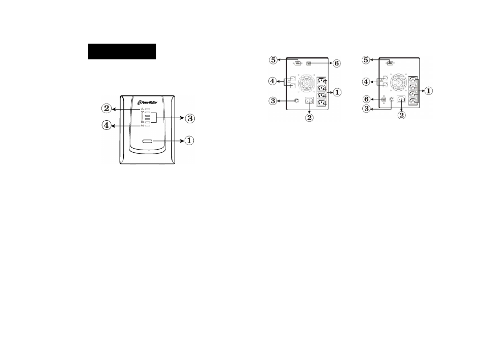
Front Panel
1.
ON/OFF Button
Press the On/Off button to turn on or off
2.
Fault LED
- The Fault LED will be on and beeps continuously when the UPS is at faulty condition.
3.
On-Line Indicator
- Load Level LEDs
Backup Indicator
- Battery Capacity LEDs
4. On-Line Indicator
- The green light indicator illuminates when the input line voltage is normal
Backup Indicator
- The green light indicator flashes when the internal battery is being used
Back Panel
1.
Battery Power Supplied Receptacle
The power supplied receptacles are used for battery to power up your equipments
while AC is failure.
2. AC Input Power Receptacle
The power receptacle is used to plug in the power cord that provides power to the
UPS
3. Circuit Breaker
The circuit breaker is used to protect your equipment against the event of short-circuit
or system overload
4. Telephone/Fax/Modem Surge Suppression Port
This surge suppression port is used to protect the telephone or modem line while
connecting the INTERNET service
5. RS-232 Communication Port
This communication port is used to communicate with a computer or modem and
support the operating systems
6. USB Communication Port (optional)
This USB communication port is used by downloaded software
3. OVERVIEW
1000VA
1400VA/2000VA