PowerWalker VFI 20000TP 3_3 BE User Manual
Page 32
27
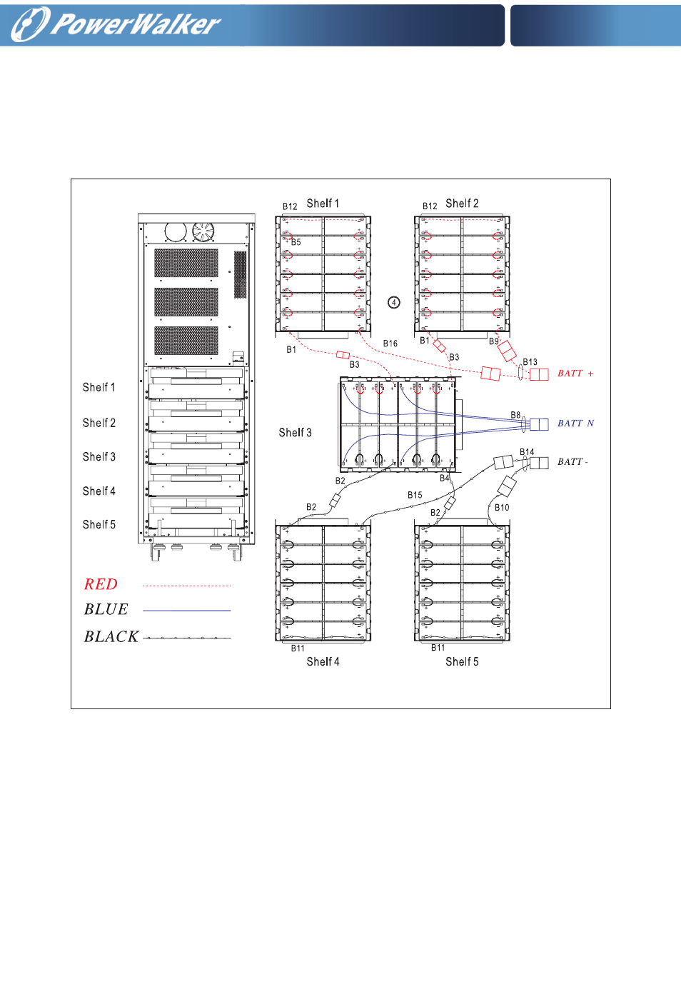
4. Connect the cables to each shelf respectively (see Fig. 2).
Remark: make sure the cables between the shelves are disconnected and the following
wire connections are done: B1, B2, B3, B4, B5, B8, B9, B10, B11, B12, B15, B16 and other
24 black cables without labels.
5. Pack the battery trays and put them into the enclosure (see Fig. 1 & Fig. 2).
6. Secure each tray with two screws.
7. Connect the cables between shelves and other two cables (B13 and B14). And then con-
nect BATT+, BATTN and BATT- to the three existing battery bus wires correspondingly.
REMARK: MAKE SURE TO CONNECT WIRES WITH THE SAME COLOR.
8. Tie up the wires properly (see Fig. 3)
9. Reinstall the battery cover and secure it with the six screws.
Fig. 2