Notice – PowerWalker VFI 20000TP 3_3 BE User Manual
Page 30
25
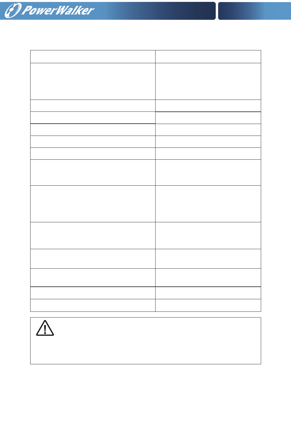
Use cable cross section and protective device specification
Model VFI 20000TP 3/3 BE/BI
Rectifier Input L1, L2, L3, N,
Bypass Input L1, L2, L3, N,
min. conductor cross section[mm ] 6
max. possible cross section[mm ] 35
Rectifier Input L1, L2, L3, N breaker (A) 60A 230VAC
Bypass Input L1, L2, L3, breaker (A) 60A 230VAC
Rectifier Input fuse (A) 60A 250VAC
Bypass Input fuse (A) 60A 250VAC
Output L1, L2, L3, N,
min. conductor cross section[mm ] 6
max. possible cross section[mm ] 35
External Battery Cabinet Positive
pole(+),Neutral pole,Negative pole (-),
min. conductor cross section[mm ] 10
max. possible cross section[mm ] 35
80A 250VDC
80A 250VDC
Protective Earthing conductor [mm ] Max 35
40A 250V AC Clearance
distances:>=1.4mm Break time<=15s
Torque for fixing above terminals 2.8-3 Nm
Internal battery fuse 100A 700VAC
External Battery Cabinet Fuse (A) in
Positive pole(+),Neutral pole,
Negative pole (-),
External Battery Cabinet breaker (A) in Posi-
tive pole(+),Neutral pole,Negative pole (-),
Backfeed protection device
2
2
2
2
2
2
2
Notice!
The following label must be displayed on all switching devices installed in the same
electrical system as the UPS, even when these are located at a distance from the area
in which it is located (according to European standard EN 62040-1-1).