Table 3. summary of fault protection and recovery – Rainbow Electronics MAX9921 User Manual
Page 13
MAX9921
Dual, 2-Wire Hall-Effect Sensor Interface
with Diagnostics
______________________________________________________________________________________
13
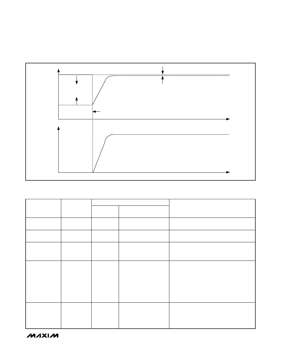
14V
V
IN_
I
IN_
0V
V
BAT
- 500mV
8V
4mA/
μs
11.5mA
0A
TIME
TIME
HALL INPUT
RECONNECTED
TO HALL SENSOR
Figure 6. Hall Input Re-Energized When Open Input is Reconnected to Hall Sensor
MAX9921 ACTIONS
FAULT
DESCRIPTION
CRITERION
ERR
OUTPUT
HALL INPUT RESPONSE
COMMENT/RECOVERY
V
BAT
< 6V
—
Asserted low
Shutoff current to both Hall
sensors
Both IN1 and IN2 are restarted with blanking
cycle when V
BAT
returns to proper range.
V
BAT
> 18V
—
Asserted low
Shutoff current to both Hall
sensors
Both IN1 and IN2 are restarted with blanking
cycle when V
BAT
returns to proper range.
Hall input open
I
IN
< 2mA
Asserted low
Shutoff current to
corresponding Hall sensor
When a Hall input is again loaded, terminating
open input condition, the Hall input are restarted
with blanking cycle.
Hall input shorted
to battery
V
IN
> V
BAT
due
to external
reverse-battery
protection
diode
Asserted low
Shutoff current to
corresponding Hall sensor
If a Hall input is pulled more than 1V above
V
BAT
, the input may back drive current into the
BAT supply and pull V
BAT
up with it. In this
condition, current levels in the Hall inputs should
never exceed 100mA. For this reason, it is
recommended that one or more MAX9921s be
powered together and share a reverse-polarity
diode separate from other circuitry.
Hall input shorted
to ground
I
IN
> 23mA
Asserted low
Shutoff current to
corresponding Hall sensor.
50µA of pullup current is
sourced to IN1 or IN2 to
aid in troubleshooting.
A falling edge at DIAG initiates a restart with a
blanking cycle of any Hall input that has been
shut off due to a short to ground. See Hall input
short-to-ground description.
Table 3. Summary of Fault Protection and Recovery