Table 2. diagnostic truth table (diagnostic mode) – Rainbow Electronics MAX9921 User Manual
Page 11
MAX9921
Dual, 2-Wire Hall-Effect Sensor Interface
with Diagnostics
______________________________________________________________________________________
11
Hall Sensor Protection from Supply Transients
If the V
BAT
voltage is lower than 6V or exceeds 18V,
IN1 and IN2 shut off current to both Hall sensors and
ERR, OUT1, and OUT2 go low. When V
BAT
returns to
the proper range, both IN1 and IN2 restart, following a
blanking cycle.
Hall Inputs Open Condition
If either IN1 or IN2 is open (I
IN
< 2mA), the correspond-
ing input shuts off current to the Hall sensor. If IN1 or
IN2 is loaded, it exits the open input fault condition and
restarts the corresponding Hall input, following a blank-
ing cycle.
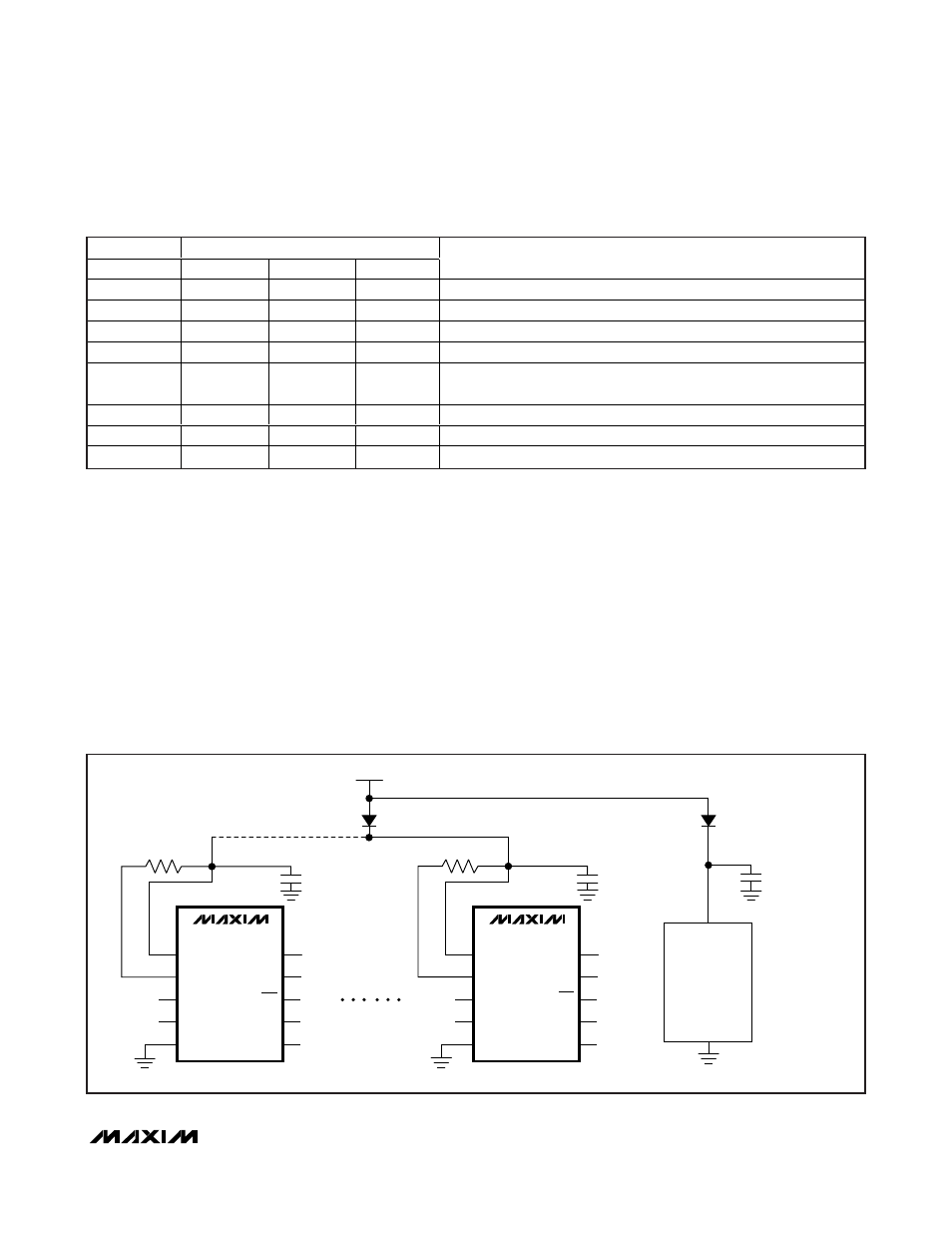
Hall Input Shorted to Battery
If either IN1 or IN2 is shorted to the battery (V
IN
> V
BAT
+ 100mV), the MAX9921 shuts off current to the corre-
sponding Hall sensor. In this case, if IN1 or IN2 is more
than 1V above V
BAT
, it may back-drive current into
BAT. In such a condition, the current level in the Hall
input should not exceed 100mA. Therefore, all the
MAX9921s together can share a separate reverse-
polarity protection diode to avoid powering up other cir-
cuitry sharing a common diode (Figure 4).
INPUT
OUTPUT
DIAG
ERR
OUT1
OUT2
DIAGNOSIS
1
0
0
0
No fault
1
0
0
1
IN1 open circuit, or IN1 open circuit and fault on IN2
1
0
1
0
IN1 shorted to battery, or IN1 shorted to battery and fault on IN2
1
0
1
1
IN1 shorted to ground, or IN1 shorted to ground and fault on IN2
1
1
0
0
V
BAT
out of range, or power-up or restart and blanking cycle (dominant
fault masks all other faults)
1
1
0
1
IN2 open circuit
1
1
1
0
IN2 shorted to battery
1
1
1
1
IN2 shorted to ground
Table 2. Diagnostic Truth Table (Diagnostic Mode)
BAT
ISET
MAX9921
IN1
IN2
GND
DIAG
OE
ERR
OUT1
OUT2
BAT
BAT
GND
OTHER
CIRCUITRY
R
ISET
BATTERY
REVERSE-POLARITY DIODE
FOR MAX9921s
REVERSE-POLARITY DIODE
FOR OTHER CIRCUITRY
R
ISET
ISET
MAX9921
IN1
IN2
GND
DIAG
OE
ERR
OUT1
OUT2
Figure 4. Several MAX9921s Connected to a Common Reverse-Polarity Diode