Pin description, Detailed description – Rainbow Electronics MAX5090C User Manual
Page 7
MAX5090A/B/C
2A, 76V, High-Efficiency MAXPower Step-Down
DC-DC Converters
_______________________________________________________________________________________
7
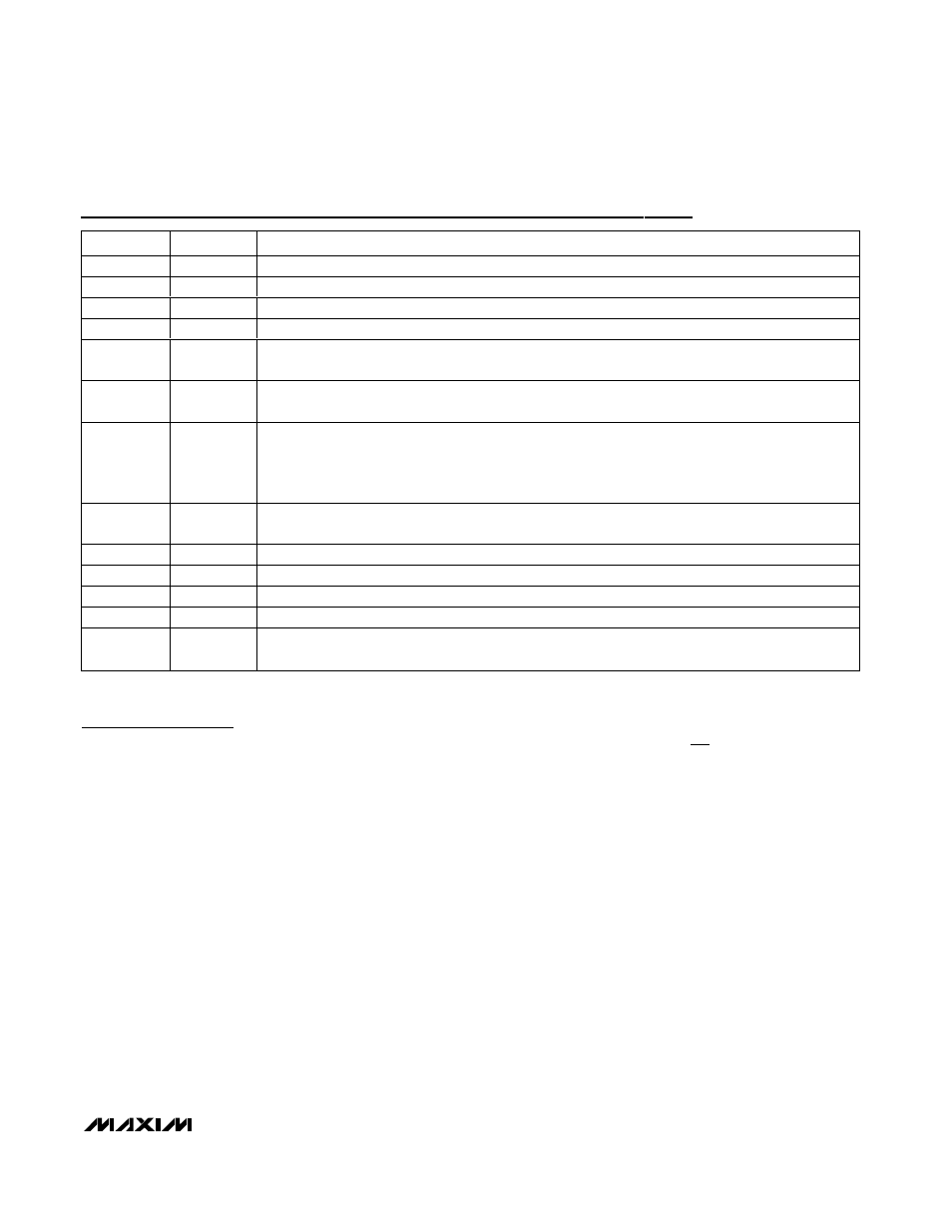
Pin Description
PIN
NAME
FUNCTION
1, 2
LX
Source Connection of Internal High-Side Switch
3
BST
Boost Capacitor Connection. Connect a 0.22µF ceramic capacitor from BST to LX.
4
V
IN
Input Voltage. Bypass V
IN
to SGND with a low-ESR capacitor as close to the device as possible.
5
VD
Internal Regulator Output. Bypass VD to PGND with a 3.3µF/10V or greater ceramic capacitor.
6
SYNC
Synchronization Input. Connect SYNC to an external clock for synchronization. Connect to SGND to
select the internal 127kHz switching frequency.
7
SS
Soft-Start Capacitor Connection. Connect an external capacitor from SS to SGND to adjust the soft-
start time.
8
FB
Output Sense Feedback Connection.
For fixed output voltage (MAX5090A/MAX5090B), connect FB to V
OUT
.
For adjustable output voltage (MAX5090C), use an external resistive voltage-divider to set V
OUT
. V
FB
regulating set point is 1.228V.
9
ON/OFF
Shutdown Control Input. Pull ON/OFF low to put the device in shutdown mode. Drive ON/OFF high for
normal operation. Connect ON/OFF to V
IN
with short leads for always-on operation.
10
SGND
Signal Ground. SGND must be connected to PGND for proper operation.
11, 15, 16
N.C.
No Connection. Not internally connected.
12
PGND
Power Ground
13, 14
DRAIN
Internal High-Side Switch Drain Connection
—
EP
Exposed Pad. Solder EP to SGND plane to aid in heat dissipation. Do not use as the only electrical
ground connection.
Detailed Description
The MAX5090 step-down DC-DC converter operates
from a 6.5V to 76V input voltage range. A unique volt-
age-mode control scheme with voltage feed-forward
and an internal switching DMOS FET provides high effi-
ciency over a wide input voltage range. This pulse-
width-modulated converter operates at a fixed 127kHz
switching frequency or can be synchronized with an
external system clock frequency. The device also fea-
tures automatic pulse-skipping mode to provide high
efficiency at light loads. Under no load, the MAX5090
consumes only 310µA, and in shutdown mode, con-
sumes only 20µA. The MAX5090 also features under-
voltage-lockout, hiccup-mode output short-circuit
protection and thermal shutdown.
ON/
OFF
/Undervoltage Lockout (UVLO)
Use the ON/OFF function to program the external UVLO
threshold at the input. Connect a resistive voltage-
divider from V
IN
to SGND with the center node to
ON/OFF, as shown in Figure 1. Calculate the threshold
value by using the following formula:
Set the external V
UVLO(TH)
to greater than 6.45V. The
maximum recommended value for R2 is less than 1M
Ω.
ON/OFF is a logic input and can be safely driven to the
full V
IN
range. Connect ON/OFF to V
IN
for automatic
startup. Drive ON/OFF to ground to shut down the
MAX5090. Shutdown forces the internal power MOSFET
off, turns off all internal circuitry, and reduces the V
IN
supply current to 20µA (typ). The ON/OFF rising thresh-
old is 1.546V (max). Before any operation begins, the
voltage at ON/OFF must exceed 1.546V. The ON/OFF
input has 100mV hysteresis.
If the external UVLO threshold setting divider is not
used, an internal undervoltage-lockout feature monitors
the supply voltage at V
IN
and allows the operation to
start when V
IN
rises above 6.45V (max). The internal
UVLO rising threshold is set at 6.17V with 0.5V hystere-
sis. The V
IN
and V
ON/OFF
voltages must be above 6.5V
and 1.546V, respectively, for proper operation.
V
R
R
x
UVLO TH
(
)
.
=
+
1
1
2
1 38