Electrical characteristics (continued) – Rainbow Electronics MAX5090C User Manual
Page 3
MAX5090A/B/C
2A, 76V, High-Efficiency MAXPower Step-Down
DC-DC Converters
_______________________________________________________________________________________
3
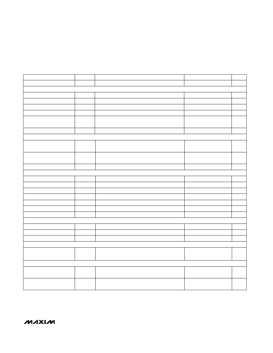
ELECTRICAL CHARACTERISTICS (continued)
(V
IN
= +12V, V
ON/OFF
= +12V, V
SYNC
= 0V, I
OUT
= 0, T
A
= T
J
= -40°C to +125°C, unless otherwise noted. Typical values are at
T
A
= +25°C. See the Typical Operating Circuit.) (Note 1)
PARAMETER
SYMBOL
CONDITIONS
MIN
TYP
MAX
UNITS
Soft-Start Reference Voltage
V
SS(REF)
1.23
1.46
1.65
V
INTERNAL SWITCH/CURRENT LIMIT
Peak Switch Current Limit
I
LIM
(Note 3)
2.4
3.3
5.0
A
Switch Leakage Current
I
OL
V
IN
= 76V, V
ON/OFF
= 0V, V
LX
= 0V
-10
+10
µA
Switch On-Resistance
R
DS(ON)
I
SWITCH
= 1A
0.26
0.4
Ω
PFM Threshold
I
PFM
Minimum switch current in any cycle
1
60
300
mA
PFM Threshold
I
PFM
Minimum switch current in any cycle at T
J
≤ +25°C
(Note 4)
14
300
mA
FB Input Bias Current
I
B
MAX5090C, V
FB
= 1.2V
-150
+0.1
+150
nA
ON/
OFF CONTROL INPUT
ON/OFF Input-Voltage
Threshold
V
ON/OFF
Rising trip point
1.180
1.38
1.546
V
ON/OFF Input-Voltage
Hysteresis
V
HYST
100
mV
ON/OFF Input Current
I
ON/OFF
V
ON/OFF
= 0V to V
IN
10
100
nA
OSCILLATOR/SYNCHRONIZATION
Oscillator Frequency
f
0SC
106
127
150
kHz
Synchronization
f
SYNC
119
200
kHz
Maximum Duty Cycle
D
MAX
V
IN
= 6.5V to 76V, V
OUT
≤ 11V
80
95
%
SYNC High-Level Voltage
2.0
V
SYNC Low-Level Voltage
0.8
V
SYNC Minimum Pulse Width
350
ns
SYNC Input Leakage
-1
+1
µA
INTERNAL VOLTAGE REGULATOR
Regulator Output Voltage
VD
V
IN
= 9V to 76V, I
OUT
= 0
7.0
7.8
8.4
V
Dropout Voltage
6.5V
≤ V
IN
≤ 8.5V, I
OUT
= 15mA
0.5
V
Load Regulation
∆VD/∆I
VD
0 to 15mA
10
Ω
PACKAGE THERMAL CHARACTERISTICS
Thermal Resistance
(Junction to Ambient)
θ
JA
TQFN package (JEDEC 51)
30
°C/W
THERMAL SHUTDOWN
Thermal-Shutdown Junction
Temperature
T
SH
Temperature rising
+175
°C
Thermal-Shutdown
Hysteresis
T
HYST
20
°C
Note 1: All limits at -40°C are guaranteed by design, not production tested.
Note 2: For total current consumption during switching (at no load), also see the Typical Operating Characteristics.
Note 3: Switch current at which the current-limit circuit is activated.
Note 4: Limits are guaranteed by design.