Rainbow Electronics MAX5090C User Manual
Page 12
MAX5090A/B/C
2A, 76V, High-Efficiency MAXPower Step-Down
DC-DC Converters
12
______________________________________________________________________________________
where:
I
OUT
is the maximum output current of the converter
and f
SW
is the oscillator switching frequency (127kHz).
For example, at V
IN
= 48V, V
OUT
= 3.3V, the ESR and
input capacitance are calculated for the input peak-to-
peak ripple of 100mV or less, yielding an ESR and
capacitance value of 40m
Ω and 100µF, respectively.
Low-ESR ceramic multilayer chip capacitors are recom-
mended for size-optimized application. For ceramic
capacitors assume the contribution from ESR and capaci-
tor discharge is equal to 10% and 90%, respectively.
The input capacitor must handle the RMS ripple current
without significant rise in the temperature. The maxi-
mum capacitor RMS current occurs at approximately
50% duty cycle. Ensure that the ripple specification of
the input capacitor exceeds the worst-case capacitor
RMS ripple current. Use the following equations to cal-
culate the input capacitor RMS current:
where:
I
PRMS
is the input switch RMS current, I
AVGin
is the
input average current, and
η is the converter efficiency.
The ESR of the aluminum electrolytic capacitor increas-
es significantly at cold temperatures. Use a 1µF or
greater value ceramic capacitor in parallel with the alu-
minum electrolytic input capacitor, especially for input
voltages below 8V.
Output Filter Capacitor
The output capacitor C
OUT
forms double pole with the
inductor and a zero with its ESR. The MAX5090’s inter-
nal fixed compensation is designed for a 100µF capaci-
tor, and the ESR must be from 20m
Ω to 100mΩ. The
use of an aluminum or tantalum electrolytic capacitor is
recommended. See Table 2 to choose an output
capacitor for stable operation.
The output ripple is comprised of
∆V
OQ
(caused by the
capacitor discharge), and
∆V
OESR
(caused by the ESR
of the capacitor). Use low-ESR tantalum or aluminum
electrolytic capacitors at the output. Use the following
equations to calculate the contribution of output capac-
itance and its ESR on the peak-to-peak output ripple
voltage:
The MAX5090 has a programmable soft-start time (t
SS
).
The output rise time is directly proportional to the out-
put capacitor, output voltage, and the load. The output
rise time also depends on the inductor value and the
current-limit threshold. It is important to keep the output
rise time at startup the same as the soft-start time (t
SS
)
to avoid output overshoot. Large output capacitors take
longer than the programmed soft-start time (t
SS
) and
cause error-amplifier saturation. This results in output
overshoot. Use greater than 2ms soft-start time for a
100µF output capacitor.
∆
∆
∆
∆
V
I x ESR
V
I
x C
x f
OESR
L
OQ
L
OUT
SW
=
≈
8
I
I
I
x
D
I
V
I
V
x
I
I
I
I
I
I
D
V
V
PRMS
PK
DC
IPK xIDC
AVGin
OUT x
OUT
IN
PK
OUT
L
DC
OUT
L
OUT
IN
=
+
=
=
+
=
−
=
+
(
)
2
2
3
2
2
η
∆
∆
I
I
I
CRMS
PRMS
AVGin
=
−
2
2
∆I
V
V
V
V
f
L
D
V
V
L
IN
OUT
OUT
IN
SW
OUT
IN
=
−
Ч
Ч
Ч
=
(
)
ESR
V
I
I
C
I
D
D
V
f
IN
ESR
OUT
L
IN
OUT
Q
SW
=
+
=
Ч
−
Ч
∆
∆
∆
2
1
(
)
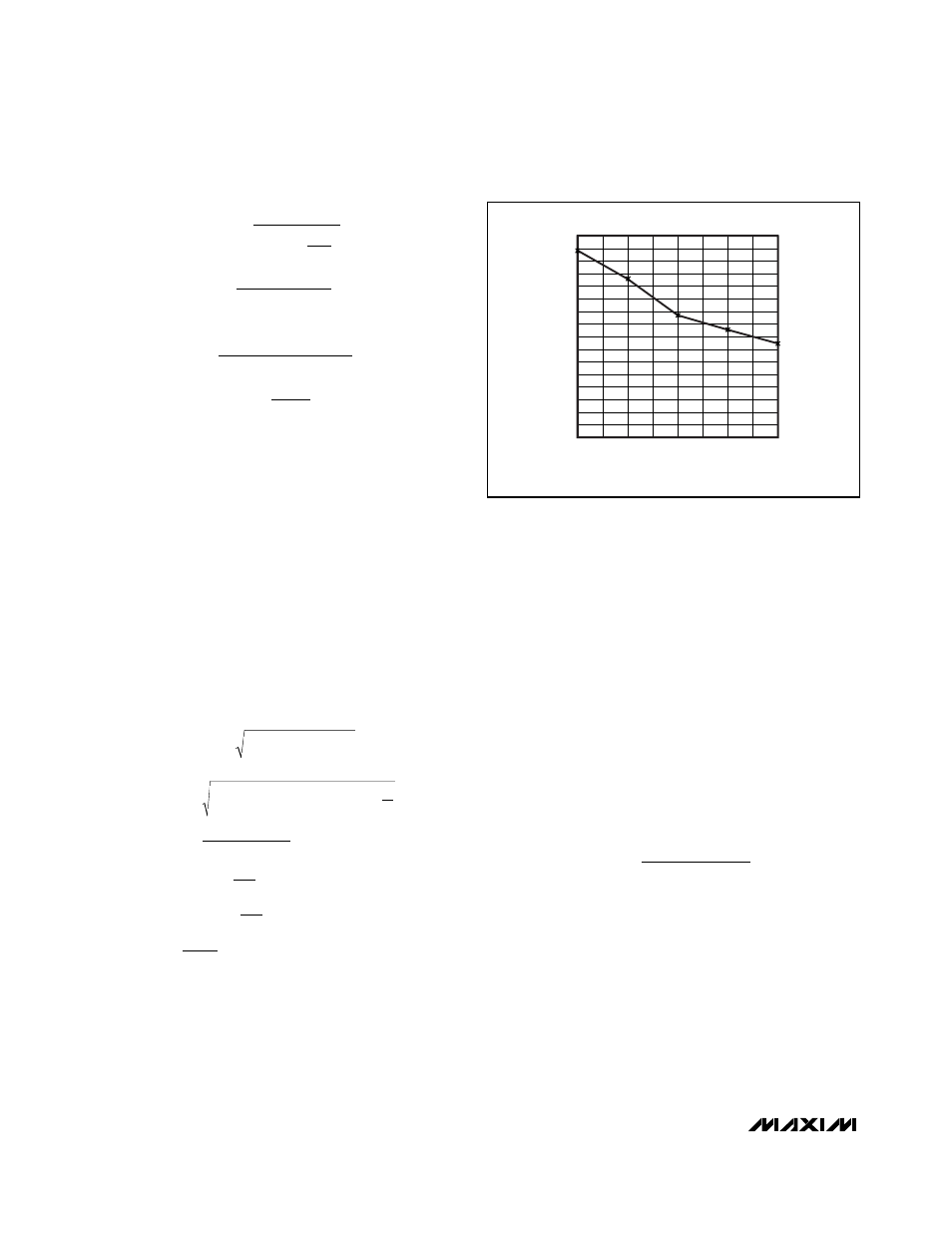
0
100
200
300
400
500
600
700
800
-40
100
25
125
150
TEMPERATURE (
°C)
V
F_D1
(mV)
Figure 3. Forward-Voltage Drop vs. Temperature of the Internal
Body Diode of MAX5090