Table 1. diode selection – Rainbow Electronics MAX5090C User Manual
Page 11
MAX5090A/B/C
2A, 76V, High-Efficiency MAXPower Step-Down
DC-DC Converters
______________________________________________________________________________________
11
Thermal-overload protection is intended to protect the
MAX5090 in the event of a fault condition. For normal
circuit operation, do not exceed the absolute maximum
junction temperature rating of T
J
= +150°C.
Setting the Output Voltage
The MAX5090A/MAX5090B have preset output volt-
ages of 3.3V and 5.0V, respectively. Connect FB to
V
OUT
for the preset output voltage (Figure 1).
The MAX5090C offers an adjustable output voltage. Set
the output voltage with a resistive divider connected
from the circuit’s output to ground (Figure 2). Connect
the center node of the divider to FB. Choose R4 less
than 15k
Ω, then calculate R3 as follows:
The MAX5090 features internal compensation for opti-
mum closed-loop bandwidth and phase margin.
Because of the internal compensation, the output must
be sensed immediately after the primary LC.
Inductor Selection
The MAX5090 is a fixed-frequency converter with fixed
internal frequency compensation. The internal fixed
compensation assumes a 100µH inductor and 100µF
output capacitor with 50m
Ω ESR. It relies on the loca-
tion of the double LC pole and the ESR zero frequency
for proper closed-loop bandwidth and the phase mar-
gin at the closed-loop unity-gain frequency. See Table
2 for proper component values. Usually, the choice of
an inductor is guided by the voltage difference
between V
IN
and V
OUT
, the required output current and
the operating frequency of the circuit. However, use the
recommended inductors in Table 2 to ensure stable
operation with optimum bandwidth.
Use an inductor with a maximum saturation current rat-
ing greater than or equal to the maximum peak current
limit (5A). Use inductors with low DC resistance for a
higher efficiency converter.
Selecting a Rectifier
The MAX5090 requires an external Schottky rectifier as
a freewheeling diode. Connect this rectifier close to the
device using short leads and short PC board traces.
The rectifier diode must fully conduct the inductor cur-
rent when the power FET is off to have a full rectifier
function. Choose a rectifier with a continuous current
rating greater than the highest expected output current.
Use a rectifier with a voltage rating greater than the
maximum expected input voltage, V
IN
. Use a low for-
ward-voltage Schottky rectifier for proper operation and
high efficiency. Avoid higher than necessary reverse-
voltage Schottky rectifiers that have higher forward-volt-
age drops. Use a Schottky rectifier with forward-voltage
drop (V
F
) less than 0.55V and 0.45V at +25°C and
+125°C, respectively, and at maximum load current to
avoid forward biasing of the internal parasitic body
diode (LX to ground). See Figure 3 for forward-voltage
drop vs. temperature of the internal body diode of the
MAX5090. Internal parasitic body-diode conduction
may cause improper operation, excessive junction tem-
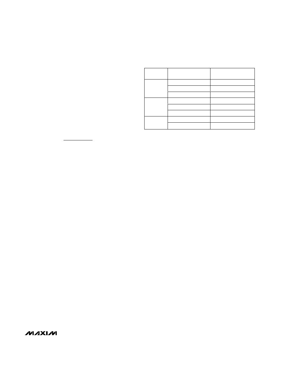
perature rise, and thermal shutdown. Use Table 1 to
choose the proper rectifier at different input voltages
and output current.
Input Bypass Capacitor
The discontinuous input current waveform of the buck
converter causes large ripple currents in the input
capacitor. The switching frequency, peak inductor cur-
rent, and the allowable peak-to-peak voltage ripple
reflecting back to the source dictate the capacitance
requirement. The MAX5090 high switching frequency
allows the use of smaller value input capacitors.
The input ripple is comprised of
∆V
Q
(caused by the
capacitor discharge) and
∆V
ESR
(caused by the ESR of
the capacitor). Use low-ESR aluminum electrolytic
capacitors with high-ripple current capability at the input.
Assuming that the contribution from the ESR and capaci-
tor discharge is equal to 90% and 10%, respectively, cal-
culate the input capacitance and the ESR required for a
specified ripple using the following equations:
R3
=
−
(
.
)
.
V
x R
OUT
1 228
1 228
4
Table 1. Diode Selection
V
IN
(V)
DIODE PART
NUMBER
MANUFACTURER
B340LB
Diodes Inc.
RB051L-40
Central Semiconductor
6.5 to 36
MBRS340T3
ON Semiconductor
MBRM560
Diodes Inc.
RB095B-60
Central Semiconductor
6.5 to 56
MBRD360T4
ON Semiconductor
50SQ80
IR
6.5 to 76
PDS5100H
Diodes Inc.