On/off control (en), Undervoltage lockout, Startup sequence (onl_, seq) – Rainbow Electronics MAX1531 User Manual
Page 21
MAX1530/MAX1531
Multiple-Output Power-Supply Controllers for
LCD Monitors
______________________________________________________________________________________
21
loads. For example, when switched at 500kHz, large
MOSFETs with a total of 40nC total gate charge would
require 40nC
× 500kHz, which is approximately 20mA.
On/Off Control (EN)
The EN pin has an accurate 1.238V (typ) rising thresh-
old with 5% hysteresis. The accurate threshold allows it
to be used to monitor the input voltage or other analog
signals of interest. If V
EN
voltage is less than its thresh-
old, then the step-down regulator and all linear regula-
tors are turned off. VL and the internal reference remain
active when EN is low to allow an accurate EN thresh-
old. A rising edge on the pin clears any latched faults
except for a thermal fault, which is cleared only by
cycling the input power.
Undervoltage Lockout
If VL drops below 3.4V (typ), the MAX1530/MAX1531
assume that the supply voltage is too low to make valid
decisions. Therefore, the undervoltage lockout (UVLO)
circuitry turns off all the internal bias supplies. Switching
is inhibited, and the DL and DH gate drivers are forced
low. After VL rises above 3.5V (typ), the fault and thermal
shutdown latches are cleared and startup begins if EN is
above its threshold.
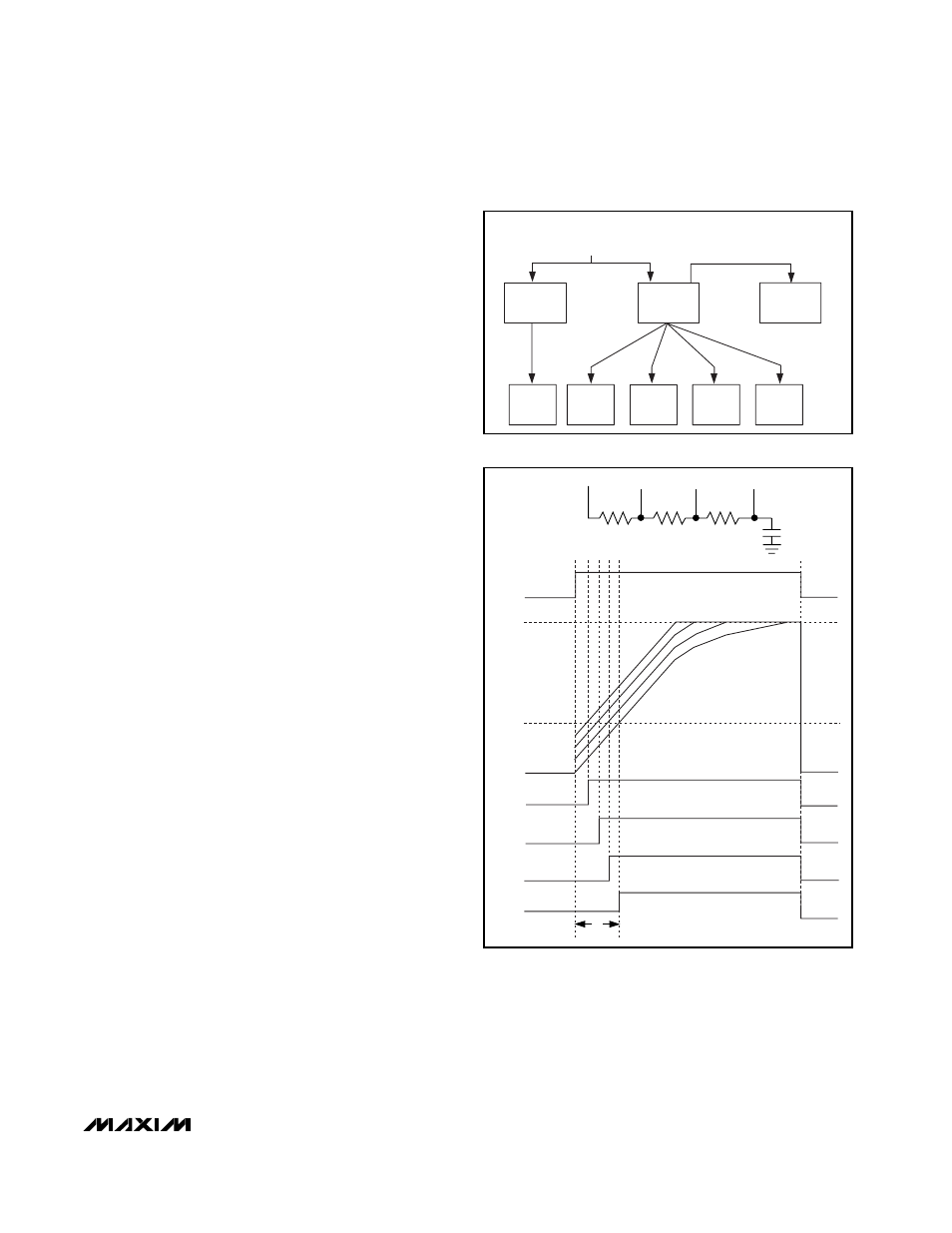
Startup Sequence (ONL_, SEQ)
The MAX1530/MAX1531 are not enabled unless all four
of the following conditions are met: 1) VL exceeds the
UVLO threshold, 2) EN is above 1.238V, 3) the fault
latch is not set, and 4) the thermal shutdown latch is not
set. After all four conditions are met, the step-down con-
troller starts switching and enables soft-start (Figure 5).
After the step-down regulator soft-start is done, the low-
voltage logic linear regulator controller (LR1) soft-starts.
The remaining linear regulator controllers and the
sequence block that can be used to control them are
enabled at the same time as the step-down regulator.
The SEQ logic input is used in combination with the
ONL_ pins to control the startup sequence. When SEQ
is high and the sequence block is enabled, each ONL_
pin sources 2µA (typ). When the voltage on an ONL_
pin reaches 1.238V (typ), its respective linear regulator
controller (LR_) is enabled. When SEQ is low or the
sequence block is not enabled, each ONL_ pin is con-
nected to ground through a 1.5k
Ω internal MOSFET.
The sequence block allows the user to program the
startup of LR2 to LR5 in any desired sequence. If no
capacitor is placed on an ONL_ pin, its LR_ controller
starts immediately after the sequence block is enabled
and SEQ goes high. Placing a 1.5nF capacitor on an
ONL_ pin provides about 1ms delay for the respective
LR_ controller. Placing different size capacitors on
each ONL_ pin allows any arbitrary startup sequence.
An arbitrary startup sequence can also be created with
a single capacitor (Figure 6). Capacitor C1, together
with the 8µA current (2µA per ONL_ pin), is chosen to
provide the desired delay for the controller that starts
last (ONLd). Using 0.1µF for C1 provides about 16ms
Figure 6. Single-Capacitor Sequence Configuration
SEQ
ONL_
0V
1.238V
5V
LRa
LRb
LRc
LRd
ON
ON
ON
ON
OFF
OFF
OFF
OFF
OFF
OFF
OFF
OFF
16ms
ONLa ONLb ONLc
ONLd
ONLa
ONLb
ONLc
ONLd
R2
75k
Ω
R3
150k
Ω
R1
51k
Ω
C1
0.1
µF
Figure 5. Startup Conditions
ONL_
CURRENT
SOURCES ON
SEQUENCE
BLOCK
ENABLED
LR5
STARTUP
LR4
STARTUP
LR2
STARTUP
LR1
STARTUP
SEQ = HIGH
ONL5 > 1.24V
ONL2 > 1.24V
ONL4 > 1.24V
LR3
STARTUP
STEP-DOWN
REGULATOR
STARTUP
STEP-DOWN
SOFT-START
DONE
EN > 1.24V
AND
VL > 3.5V
ONL3 > 1.24V