Static parameter definitions, Dynamic parameter definitions – Rainbow Electronics MAX1198 User Manual
Page 19
physical location of the analog ground (GND) and the
digital output driver ground (OGND) on the ADC’s
package. The two ground planes should be joined at a
single point so the noisy digital ground currents do not
interfere with the analog ground plane. The ideal loca-
tion for this connection can be determined experimen-
tally at a point along the gap between the two ground
planes, which produces optimum results. Make this
connection with a low-value, surface-mount resistor (1
Ω
to 5
Ω), a ferrite bead, or a direct short.
Alternatively, all ground pins could share the same
ground plane if the ground plane is sufficiently isolated
from any noisy, digital systems ground plane (e.g.,
downstream output buffer or DSP ground plane). Route
high-speed digital signal traces away from the sensitive
analog traces of either channel. Make sure to isolate
the analog input lines to each respective converter to
minimize channel-to-channel crosstalk. Keep all signal
lines short and free of 90
° turns.
Static Parameter Definitions
Integral Nonlinearity
Integral nonlinearity (INL) is the deviation of the values
on an actual transfer function from a straight line. This
straight line can be either a best-straight-line fit or a line
drawn between the endpoints of the transfer function,
once offset and gain errors have been nullified. The
static linearity parameters for the MAX1198 are mea-
sured using the best-straight-line-fit method.
Differential Nonlinearity
Differential nonlinearity (DNL) is the difference between
an actual step width and the ideal value of 1LSB. A
DNL error specification of less than 1LSB guarantees
no missing codes and a monotonic transfer function.
Dynamic Parameter Definitions
Aperture Jitter
Figure 11 depicts the aperture jitter (t
AJ
), which is the
sample-to-sample variation in the aperture delay.
Aperture Delay
Aperture delay (t
AD
) is the time defined between the
rising edge of the sampling clock and the instant when
an actual sample is taken (Figure 11).
Signal-to-Noise Ratio
For a waveform perfectly reconstructed from digital
samples, the theoretical maximum SNR is the ratio of
the full-scale analog input (RMS value) to the RMS
quantization error (residual error). The ideal, theoretical
minimum analog-to-digital noise is caused by quantiza-
tion error only and results directly from the ADC’s reso-
lution (N-bits):
SNR
dB[max]
= 6.02
dB
✕
N + 1.76
dB
MAX1198
Dual, 8-Bit, 100Msps, 3.3V, Low-Power ADC
with Internal Reference and Parallel Outputs
______________________________________________________________________________________
19
0
°
90
°
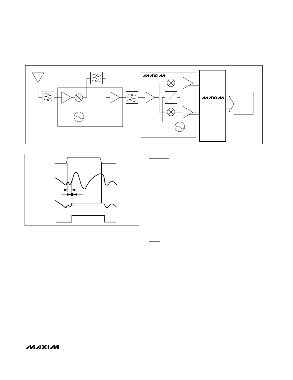
÷8
DOWNCONVERTER
MAX2451
INA+
MAX1198
INA-
INB+
INB-
DSP
POST-
PROCESSING
Figure 10. Typical QAM Application Using the MAX1198
HOLD
ANALOG
INPUT
SAMPLED
DATA (T/H)
T/H
t
AD
t
AJ
TRACK
TRACK
CLK
Figure 11. T/H Aperture Timing