Chip information, Pin configurations (continued) – Rainbow Electronics MAX1774 User Manual
Page 19
MAX1774
Dual, High-Efficiency, Step-Down
Converter with Backup Battery Switchover
______________________________________________________________________________________
19
Inductor Selection
The essential parameters for inductor selection are
inductance and current rating. The MAX1774 operates
with a wide range of inductance values.
Calculate the inductance value for either CORE or
MAIN, L
MIN
:
L
(MIN)
= (V
IN
- V
OUT
)
✕
(t
ON(MIN)
/ l
RIPPLE
)
where t
ONMIN
is typically 400ns, and l
RIPPLE
is the con-
tinuous conduction peak-to-peak l
RIPPLE
current.
In continuous conduction, l
RIPPLE
should be chosen to
be 30% of the maximum load current. With high induc-
tor values, the MAX1774 begins continuous-conduction
operation at a lower fraction of full load (see Detailed
Description).
The inductor’s saturation current must be greater than
the peak switching current to prevent core saturation.
Saturation occurs when the inductor’s magnetic flux
density reaches the maximum level the core can sup-
port and inductance starts to fall. The inductor heating
current rating must be greater than the maximum load
current to prevent overheating. For optimum efficiency,
the inductor series resistance should be less than the
current-sense resistance.
Capacitor Selection
Choose the output filter capacitors to service input and
output ripple current with acceptable voltage ripple.
ESR in the output capacitor is a major contributor to
output ripple. For the main converter, low-ESR capaci-
tors such as polymer or ceramic capacitors are recom-
mended. For the core converter, choosing a low-ESR
tantalum capacitor with enough ESR to generate about
1% ripple voltage across the output is helpful in ensur-
ing stability.
Voltage ripple is the sum of contributions from ESR and
the capacitor value:
V
RIPPLE
≈
V
RIPPLE,ESR
+ V
RIPPLE,C
For tantalum capacitors, the ripple is determined mostly
by the ESR. Voltage ripple due to ESR is:
V
RIPPLE,ESR
≈
(R
ESR
)
✕
I
RIPPLE
For ceramic capacitors, the ripple is mostly due to the
capacitance. The ripple due to the capacitance is
approximately:
V
RIPPLE,C
≈
L I
RIPPLE
2
C
OUT
V
OUT
where V
OUT
is the average output voltage.
These equations are suitable for initial capacitor selec-
tion. Final values should be set by testing a prototype
or evaluation kit. When using tantalum capacitors, use
good soldering practices to prevent excessive heat
from damaging the devices and increasing their ESR.
Also, ensure that the tantalum capacitors’ surge-current
ratings exceed the startup inrush and peak switching
currents.
The input filter capacitor reduces peak currents drawn
from the power source and reduces noise and voltage
ripple at IN, caused by the circuit’s switching. Use a
low-ESR capacitor. Two smaller value low-ESR capaci-
tors can be connected in parallel if necessary. Choose
input capacitors with working voltage ratings higher
than the maximum input voltage.
MOSFET Selection
The MAX1774 drives an external enhancement-mode P-
channel MOSFET and a synchronous-rectifier N-channel
MOSFET. When selecting the MOSFETs, important para-
meters to consider are on-resistance (R
DS(ON)
), maxi-
mum drain-to-source voltage (V
DS(MAX)
), maximum
gate-to-source voltage (V
GS(MAX)
), and minimum
threshold voltage (V
TH(MIN)
).
Chip Information
TRANSISTOR COUNT: 4545
PROCESS: BiCMOS
28
27
26
25
24
23
22
21
20
19
18
17
16
15
1
2
3
4
5
6
7
8
9
10
11
12
13
14
LXC
INS
LBO
ACO
INC
GND
ACI
FBC
CS-
CS+
FBM
REF
LBI
DBI
BKOFF
BIN
LXB
CVH
PDRV
IN
CVL
NDRV
PGND
PGNDC
MDRV
BKUP
SHDNC
SHDNM
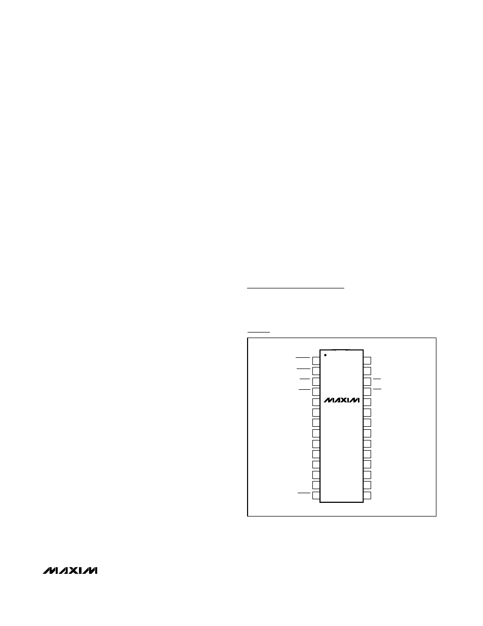
28 QSOP
TOP VIEW
MAX1774
Pin Configurations (continued)