100% duty cycle and dropout – Rainbow Electronics MAX1774 User Manual
Page 12
each cycle (see Typical Operating Characteristics). The
switch waveform may exhibit ringing, which occurs at
the resonant frequency of the inductor and stray capaci-
tance, due to the residual energy trapped in the core
when the rectifier MOSFET turns off. This ringing is nor-
mal and does not degrade circuit performance.
When delivering medium-to-high output currents, the
MAX1774 operates in PWM continuous-conduction
mode. In this mode, current always flows through the
inductor and never ramps to zero. The control circuit
adjusts the switch duty cycle to maintain regulation
without exceeding the peak switching current set by
the current-sense resistor.
100% Duty Cycle and Dropout
The MAX1774 operates with a duty cycle up to 100%,
extending the input voltage range by turning the MOS-
FET on continuously when the supply voltage ap-
proaches the output voltage. This services the load
when conventional switching regulators with less than
MAX1774
Dual, High-Efficiency, Step-Down
Converter with Backup Battery Switchover
12
______________________________________________________________________________________
PGNDC
FBC
LXC
INC
FBM
CS-
CS+
PGND
PDRV
NDRV
CVH
MAIN
C5
1
µ
F
P2
N1
L1
5
µ
H
C
MAIN
47
µ
F
C6
10
µ
F
R
CS
CORE
C
CORE
22
µ
F
R10
R11
R8
R9
L2
5.4
µ
H
C7
1
µ
F
R5
1M
Ω
R6
1M
Ω
R7
1M
Ω
GND
REF
CVL
LXB
BIN
IN
DBI
LBI
BACKUP
BATTERY
MAIN
BATTERY
V
IN_AC
R1
C1
10
µ
F
C2
10
µ
F
C4
0.22
µ
F
C3
1
µ
F
D2
EP05Q
03L
L3
22
µ
H
P1
R4
R2
R3
D1
BKOFF
BKUP
LBO
ACO
SHDNC
SHDNM
MDRV
MAX1774
ON
OFF
ON
OFF
1.0V
TO
5.5V
LXB2(QFN ONLY)
0.9V
TO
5.5V
1M
Ω
ACI
INS
FDS8928A
1.25V
TO
5.5V
NDS356AP
NSD03A10
2.7V
TO
5.5V
2.7V
TO
5.5V
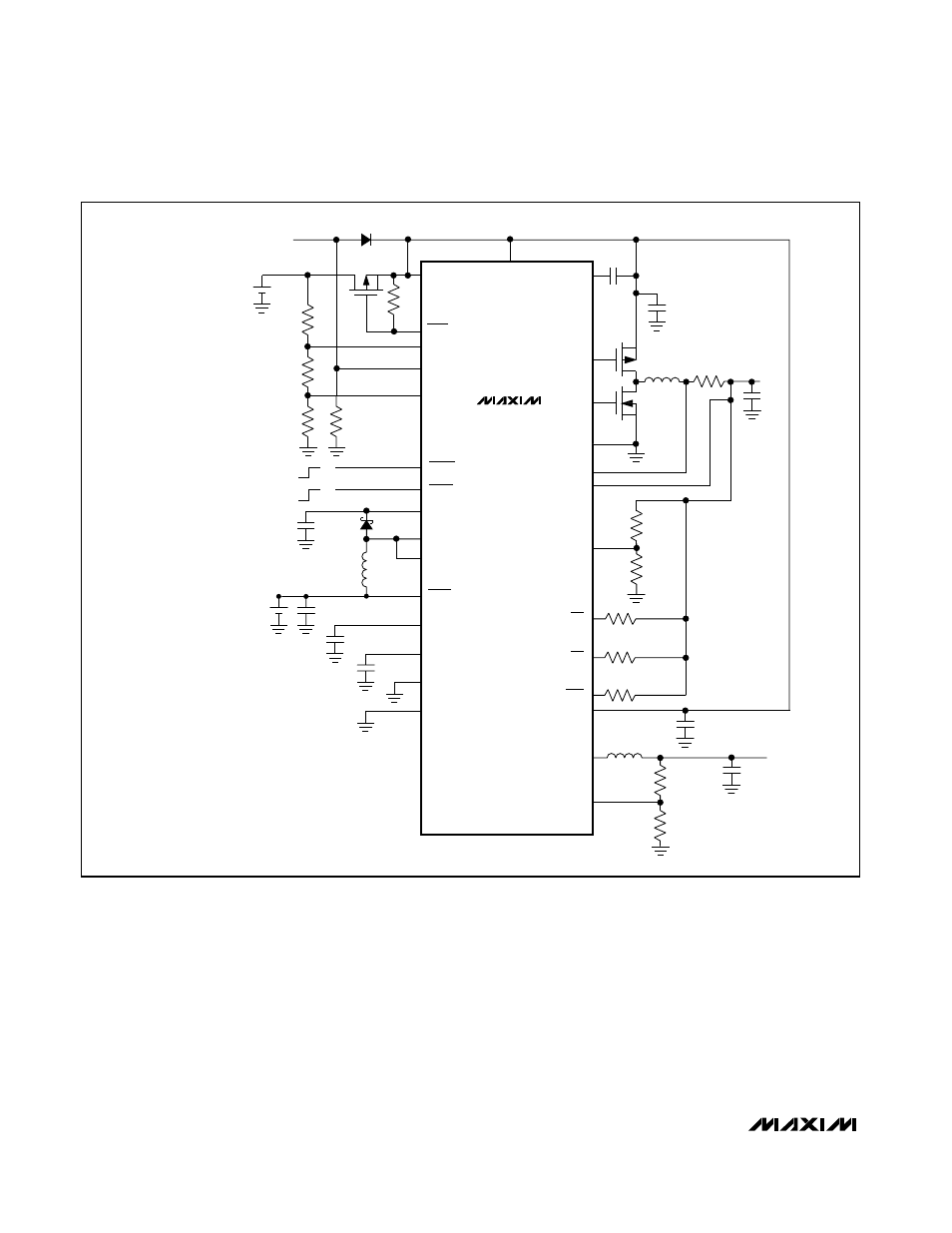
NOTE: FOR INPUT VOLTAGES
TO 28V SEE FIGURE 4
AND FIGURE 5
Figure 1. Typical Application Circuit For Low-Input Voltage Applications