Setting the voltage monitor levels – Rainbow Electronics MAX1774 User Manual
Page 18
nals, and be close together to improve noise rejection.
These traces should be used for current-sense signal
routing only and should not carry any load current.
Refer to the MAX1774 evaluation kit for layout exam-
ples.
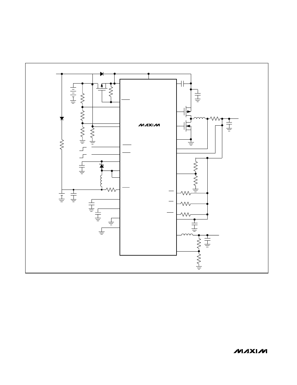
Setting the Voltage Monitor Levels
The low battery and dead battery detector trip points
can be set by adjusting the resistor values of the
divider string (R1, R2, and R3) in Figure 1 according to
the following equations:
R1 = (R2 + R3)
✕
[(V
BD
/ V
TH
) - 1]
R2 = R3
✕
[(V
BL
/ V
BD
) - 1]
where V
BL
is the low battery voltage, V
BD
is the dead
battery voltage, and V
TH
= +1.20V. Choose R3 to be
less than 250k
Ω
.
MAX1774
Dual, High-Efficiency, Step-Down
Converter with Backup Battery Switchover
18
______________________________________________________________________________________
Figure 5. Typical Application Circuit (with Recharge)
PGNDC
FBC
LXC
INC
FBM
CS-
CS+
PGND
PDRV
NDRV
CVH
MAIN
C5
L1
10
µ
H
C
MAIN
47
µ
F
R
CS
CORE
C
CORE
22
µ
F
R10
R11
R8
R9
L2
C7
1
µ
F
R5
1M
Ω
R6
1M
Ω
R7
1M
Ω
GND
REF
CVL
LXB
BIN
IN
DBI
LBI
BACKUP
BATTERY
MAIN
BATTERY
R1
R13
C2
10
µ
F
C3
C4
0.22
µ
F
C1
10
µ
F
P1
R4
R2
R3
R12
D1
BKOFF
BKUP
LBO
ACO
SHDNM
MDRV
MAX1774
L3
22
µ
H
V
IN_AC
ACI
SHDNC
C6
10
µ
F
P2
N1
ON
OFF
ON
OFF
1.0V
TO
5.5V
2.6V
TO
5.5V
FDS8928A
INS
1M
Ω
2.7V
TO
20V
2.7V
TO
28V
NDS356AP
NSD03A10
0.9V
TO
5.5V
LXB2 (QFN ONLY)
D2
EP05
Q03L