Analog considerations, Pipelined operation, Reference – Rainbow Electronics MAX118 User Manual
Page 9
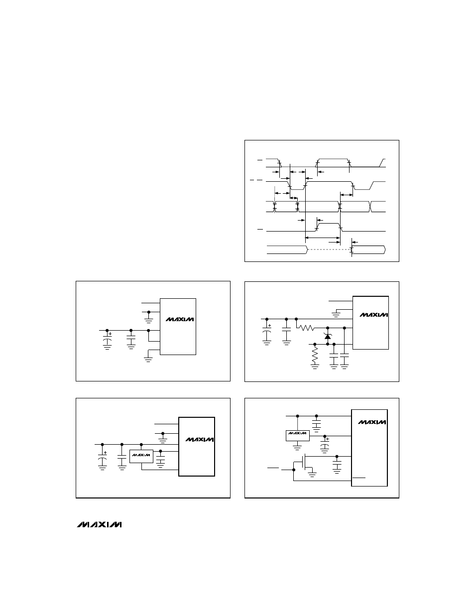
Pipelined Operation
Besides the two standard write-read-mode options,
pipelined operation can be achieved by connecting
WR to RD (Figure 6). With CS low, driving WR and RD
low initiates a conversion and concurrently reads the
result of the previous conversion.
_____________Analog Considerations
Reference
Figures 7a, 7b, and 7c show typical reference connec-
tions. The voltages at REF+ and REF- set the ADC’s
analog input range (see Figure 10). The voltage at REF-
defines the input that produces an output code of all
zeros, and the voltage at REF+ defines the input that
produces an output code of all ones.
The internal resistance from REF+ to REF- can be as
low as 1k
Ω
, and current will flow through it even when
the MAX114/MAX118 are shut down. Figure 7d shows
how an N-channel MOSFET can be connected to REF-
MAX114/MAX118
+5V, 1Msps, 4 & 8-Channel,
8-Bit ADCs with 1µA Power-Down
_______________________________________________________________________________________
9
REF-
V
DD
IN_
REF+
V
IN+
V
IN-
GND
+5V
0.1
µ
F
4.7
µ
F
MAX114
MAX118
Figure 7a. Power Supply as Reference
REF-
V
DD
MX584
IN_
REF+
V
IN+
V
IN-
GND
+5V
C1
0.1µF
0.1µF
4.7µF
MAX114
MAX118
Figure 7b. External Reference, 4.096V Full Scale
REF-
REF+
0.1µF
0.1µF
* CURRENT PATH MUST STILL
EXIST FROM V
IN-
TO GND
R*
IN_
V
IN-
V
DD
V
IN+
GND
+5V
+2.5V
4.7µF
0.1µF
MAX114
MAX118
Figure 7c. Input Not Referenced to GND
REF-
V
DD
MAX874
REF+
+5V
0.1µF
0.1µF
C1
3.3µF
PWRDN
PWRDN
N-FET*
* IRML2402
MAX114
MAX118
Figure 7d. An N-channel MOSFET switches off the reference
load during power-down
t
ACQ
t
INTL
RD, WR
INT
NEW DATA (N)
t
WR
t
ACQ
t
AH
t
CSH
t
IHWR
t
CSS
t
ID
OLD DATA (N - 1)
D0–D7
ADDRESS
VALID (N)
ADDRESS
VALID (N + 1)
A0–A2
CS
Figure 6. Pipelined Mode Timing (
WR = RD) (MODE = 1)