Logic electrical characteristics, 0 functional description, Lm77 – Rainbow Electronics LM77 User Manual
Page 7
Logic Electrical Characteristics
(Continued)
1.0 Functional Description
The LM77 temperature sensor incorporates a band-gap type
temperature sensor, 10-bit ADC, and a digital comparator
with user-programmable upper and lower limit values. The
comparator activates either the INT line for temperatures
outside the T
LOW
and T
HIGH
window, or the T_CRIT_A line
for temperatures which exceed T_CRIT. The lines are pro-
grammable for mode and polarity.
1.1 TEMPERATURE COMPARISON
LM77 provides a window comparison against a lower (T
LOW
)
and upper (T
HIGH
) trip point. A second upper trip point
(T_CRIT) functions as a critical alarm shutdown.
Figure 3
depicts the comparison function as well as the modes of
operation.
1.1.1 STATUS BITS
The internal Status bits operate as follows:
“True”:
Temperature above a T
HIGH
or T_CRIT is “true” for
those respective bits. A “true” for T
LOW
is temperature below
T
LOW
.
“False”:
Assuming temperature has previously crossed
above T
HIGH
or T_CRIT, then the temperature must drop
below the points corresponding T
HYST
(T
HIGH
− T
HYST
or
T_CRIT − T
HYST
) in order for the condition to be false. For
T
LOW
, assuming temperature has previously crossed below
T
LOW
, a “false” occurs when temperature goes above T
LOW
+ T
HYST
.
The Status bits are not affected by reads or any other
actions, and always represent the state of temperature vs.
setpoints.
1.1.2 HARDWIRE OUTPUTS
The T_CRIT_A hardwire output mirrors the T_CRIT_A flag,
when the flag is true, the T_CRIT_A output is asserted at all
times regardless of mode. Reading the LM77 has no effect
on the T_CRIT_A output, although the internal conversion is
restarted.
The behavior of the INT hardwire output is as follows:
Comparator Interrupt Mode (Default):
User reading part
resets output until next measurement completes. If condition
is still true, output is set again at end of next conversion
cycle. For example, if a user never reads the part, and
temperature goes below T
LOW
then INT becomes active. It
would stay that way until temperature goes above T
LOW
+
T
HYST
. However if the user reads the part, the output would
be reset. At the end of the next conversion cycle, if the
condition is true, it is set again. If not, it remains reset.
Event Interrupt Mode:
User reading part resets output
until next condition
″
event
″
occurs (in other words, output is
only set once for a true condition, if reset by a read, it
remains reset until the next triggering threshold has been
crossed). Conversely, if a user never read the part, the
output would stay set indefinitely after the first event that set
the output. An “event” for Event Interrupt Mode is defined as:
1.
Transitioning upward across a setpoint, or
2.
Transitioning downward across a setpoint’s correspond-
ing hysteresis (after having exceeded that setpoint).
For example, if a user never read the part, and temperature
went below T
LOW
then INT would become active. It would
stay that way forever if a user never read the part.
However if the user read the part, the output would be reset.
Even if the condition is true, it will remain reset. The tem-
perature must cross above T
LOW
+ T
HYST
to set the output
again.
In either mode, reading any register in the LM77 restarts the
conversion. This allows a designer to know exactly when the
LM77 begins a comparison. This prevents unnecessary In-
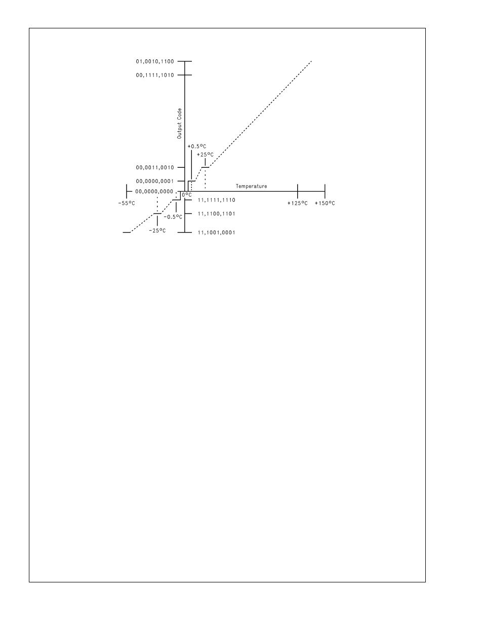
DS100136-5
FIGURE 2. Temperature-to-Digital Transfer Function (Non-linear scale for clarity)
LM77
www.national.com
7