0 functional description, Lm77 – Rainbow Electronics LM77 User Manual
Page 11
1.0 Functional Description
(Continued)
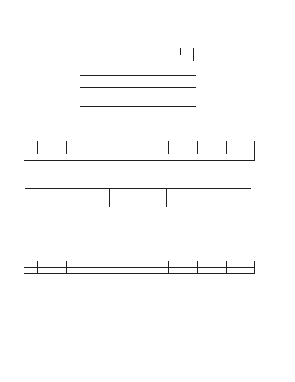
1.9 POINTER REGISTER
(Selects which registers will be read from or written to):
P7
P6
P5
P4
P3
P2
P1
P0
0
0
0
0
0
Register Select
P0–P2: Register Select:
P2
P1
P0
Register
0
0
0
Temperature (Read only) (Power-up
default)
0
0
1
Configuration (Read/Write)
0
1
0
T
HYST
(Read/Write)
0
1
1
T_CRIT (Read/Write)
1
0
0
T
LOW
(Read/Write)
1
0
1
T
HIGH
(Read/Write)
P3–P7: Must be kept zero.
1.10 TEMPERATURE REGISTER
(Read Only):
D15
D14
D13
D12
D11
D10
D9
D8
D7
D6
D5
D4
D3
D2
D1
D0
Sign
Sign
Sign
Sign
MSB
Bit 7
Bit 6
Bit 5
Bit 4
Bit 3
Bit 2
Bit 1
Bit 0
CRIT
HIGH
LOW
Status Bits
D0–D2: Status Bits
D3–D15: Temperature Data. One LSB = 0.5˚C. Two’s complement format.
1.11 CONFIGURATION REGISTER
(Read/Write):
D7
D6
D5
D4
D3
D2
D1
D0
0
0
0
Fault Queue
INT Polarity
T_CRIT_A
Polarity
INT Mode
Shutdown
D0: Shutdown - When set to 1 the LM77 goes to low power shutdown mode. Power up default of “0”.
D1: Interrupt mode - 0 is Comparator Interrupt mode, 1 is Event Interrupt mode. Power up default of “0”.
D2, D3: T_CRIT_A and INT Polarity - 0 is active low, 1 is active high. Outputs are open-drain. Power up default of “0”
D4: Fault Queue - When set to 1 the Fault Queu is enabled,
see
Section 1.7. Power up default of “0”.
D5–D7: These bits are used for production testing and must be kept zero for normal operation.
1.12 T
HYST
, T
LOW
, T
HIGH
AND T_CRIT_A REGISTERS
(Read/Write):
D15
D14
D13
D12
D11
D10
D9
D8
D7
D6
D5
D4
D3
D2
D1
D0
Sign
Sign
Sign
Sign
MSB
Bit7
Bit6
Bit5
Bit 4
Bit 3
Bit 2
Bit 1
Bit 0
X
X
X
D0–D2: Undefined
D3–D15: T
HYST
, T
LOW
, T
HIGH
or T_CRIT Trip Temperature Data. Power up default is T
LOW
= 10˚C, T
HIGH
= 64˚C, T_CRIT = 80˚C,
T
HYST
= 2˚C.
T
HYST
is subtracted from T
HIGH
, and T_CRIT, and added to T
LOW
.
Avoid programming setpoints so close that their hysteresis values overlap. See
Section 1.1.
LM77
www.national.com
11