Rainbow Electronics MAX998 User Manual
Page 7
MAX976/MAX978/MAX998
Single/Dual/Quad, SOT23, Single-Supply,
High-Speed, Low-Power Comparators
_______________________________________________________________________________________
7
2) Choose the hysteresis band required (V
HB
). For this
example, choose 100mV.
3) Calculate R1. R1 = R3 x (V
HB
/ V
CC
). Plugging in the
values for this example,
R1 = 1.2M
Ω
x (100mV / 5.0V) = 24k
Ω
4) Choose the trip point for V
IN
rising. This is the
threshold voltage at which the comparator switches
from low to high as V
IN
rises above the trip point. In
this example, choose 3.0V.
5) Calculate R2 as follows:
Choose a standard value for R2 of 16k
Ω
.
6) Verify the trip voltage and hysteresis as follows:
IR Receiver
The
Typical Operating Circuit
shows an application using
the MAX998 as an infrared receiver. The infrared photo-
diode creates a current relative to the amount of infrared
light present. This current creates a voltage across R
D
.
When this voltage level crosses the voltage applied by the
voltage divider to the inverting input, the output transitions.
Window Comparator
The MAX976 is ideal for making a window detector
(undervoltage/overvoltage detector). The schematic
shown in Figure 3 uses a MAX6120 reference and com-
ponent values selected for a 2.0V undervoltage thresh-
old and a 2.5V overvoltage threshold. Choose different
thresholds by changing the values of R1, R2, and R3.
OUTA provides an active-low undervoltage indication,
and OUTB gives an active-low overvoltage indication.
ANDing the two outputs provides an active-high,
power-good signal. The design procedure is as follows:
1) Select R1. The leakage current into INB- is normally
75nA, so the current through R1 should exceed
1.0µA for the thresholds to be accurate. R1 values in
the 50k
Ω
to 100k
Ω
range are typical.
2) Choose the overvoltage threshold (V
OTH
) when V
IN
is rising, and calculate R2 and R3 with the following
formula:
R
SUM
= R2 + R3 = R1 x [V
OTH
/ (V
REF
+ V
H
) - 1]
where V
H
= 1/2V
HYST
.
3) Choose the undervoltage threshold (V
UTH
) when V
IN
is falling, and calculate R2 with the following formula:
R2 = (R1 + R
SUM
) x [(V
REF
- V
H
) / V
UTH
] - R1
where V
H
= 1/2V
HYST
.
4) Calculate R3 with the following formula:
R3 = (R
SUM
) - R2
5) Verify the resistor values. The equations are as follows:
V
OTH
= (V
REF
+ V
H
) x (R1 + R2 + R3) / R1
V
UTH
= (V
REF
- V
H
) x (R1 + R2 + R3) / (R1 + R2)
V rising: V
= V
x R1 x
1
R1
V falling
IN
THR
REF
IN
:
+
+
=
−
=
−
1
2
1
3
1
3
R
R
V
V
R x V
R
Hysteresis
V
V
THF
THR
CC
THR
THF
R2 =
1
V
V
x R1
1
R1
1
R3
R2 =
1
3.0V
1.2 x 24k
1
24k
1
1.2M
16.2k
THR
REF
−
−
−
−
=
Ω
Ω
Ω
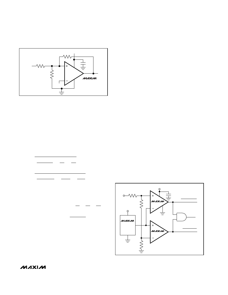
V
CC
MAX976
MAX978
MAX998
OUT
0.1
µ
F
R3
R1
R2
V
REF
GND
V
IN
V
CC
Figure 2. Additional Hysteresis
3
1
3
4
R3
82.1k, 1%
V
CC
V
IN
R2
24.9k,
1%
R1
100k,
1%
2
6
OVERVOLTAGE
UNDERVOLTAGE
POWER GOOD
1/2
MAX976
MAX6120
1
2
V
CC
8
7
5
0.1
µ
F
1/2
MAX976
Figure 3. Window Comparator