Rainbow Electronics MAX868 User Manual
Page 7
Capacitor Selection
Choosing the Flying Capacitors
Proper choice of the flying capacitors is dependent pri-
marily upon the desired output current. For flying capaci-
tors in the 0.1µF to 0.33µF range, the maximum output
current can be approximated by the following equation:
where f
MAX
is the maximum oscillator frequency (typically
450kHz), R
OUT
is the MAX868 open-loop output
impedance (typically 70
Ω
), and C1 and C2 are the flying-
capacitor values. As a general rule, choose the lowest-
value flying capacitors that provide the desired output
current in order to minimize output voltage ripple (see the
section
Choosing the Output Capacitor
).
Surface-mount ceramic capacitors are preferred, due
to their small size, low cost, and low equivalent series
resistance (ESR). To ensure proper operation over the
entire temperature range, choose ceramic capacitors
with X7R (or equivalent) low temperature-coefficient
(tempco) dielectrics. See Table 1 for a list of suggested
capacitor suppliers.
Choosing the Output Capacitor
The output capacitor stores the charge transferred from
the flying capacitors and services the load between
oscillator cycles. A good general rule is to make the
output capacitance at least ten times greater than that
of the flying capacitors.
The output voltage ripple is dependent upon the
capacitance of the flying capacitor and upon the output
capacitor’s capacitance and ESR. When operating in
closed-loop mode (when the MAX868 is generating a
regulated output voltage), use the following equation to
approximate peak-to-peak output voltage ripple:
where C1 and C2 are the flying capacitors, R
ESR
is the
output capacitor’s ESR, and R
OUT
is the MAX868’s
open-loop output impedance, typically 70
Ω
.
Choose a low-ESR output capacitor for minimum output
ripple. Surface-mount ceramic capacitors are preferred
for their small size, low cost, and low ESR; low-ESR tan-
talum electrolytic capacitors are also acceptable. When
using a ceramic output capacitor, ensure proper opera-
tion over the entire temperature range by choosing a
capacitor with X7R (or equivalent) low tempco dielec-
tric. See Table 1 for a list of suggested capacitor sup-
pliers.
V
2 x V
V
x
1
1
4 x C
C1
C2
R
R
RIPPLE
IN
OUT
OUT
ESR
OUT
|
|
=
−
(
)
+
+
+
I
2 x V
V
4
f
x C1
C2
+ R
x
10V
V
V
OUT(MAX)
IN
OUT
MAX
OUT
IN
OUT
|
|
|
|
=
−
+
+
(
)
MAX868
Regulated, Adjustable -2x
Inverting Charge Pump
_______________________________________________________________________________________
7
Table 1. Manufacturers of Surface-Mount, Low-ESR Capacitors
Sprague
TYPE
Matsuo
AVX
Surface-Mount Tantalum
MANUFACTURER
593D, 595D series
267 series
TPS series
PART
(603) 224-1430
(714) 960-6492
(803) 626-3123
FAX
(603) 224-1961
(714) 969-2491
(803) 946-0690
PHONE
X7R type
X7R type
(714) 960-6492
(803) 626-3123
(714) 969-2491
(803) 946-0690
Matsuo
Surface-Mount Ceramic
AVX
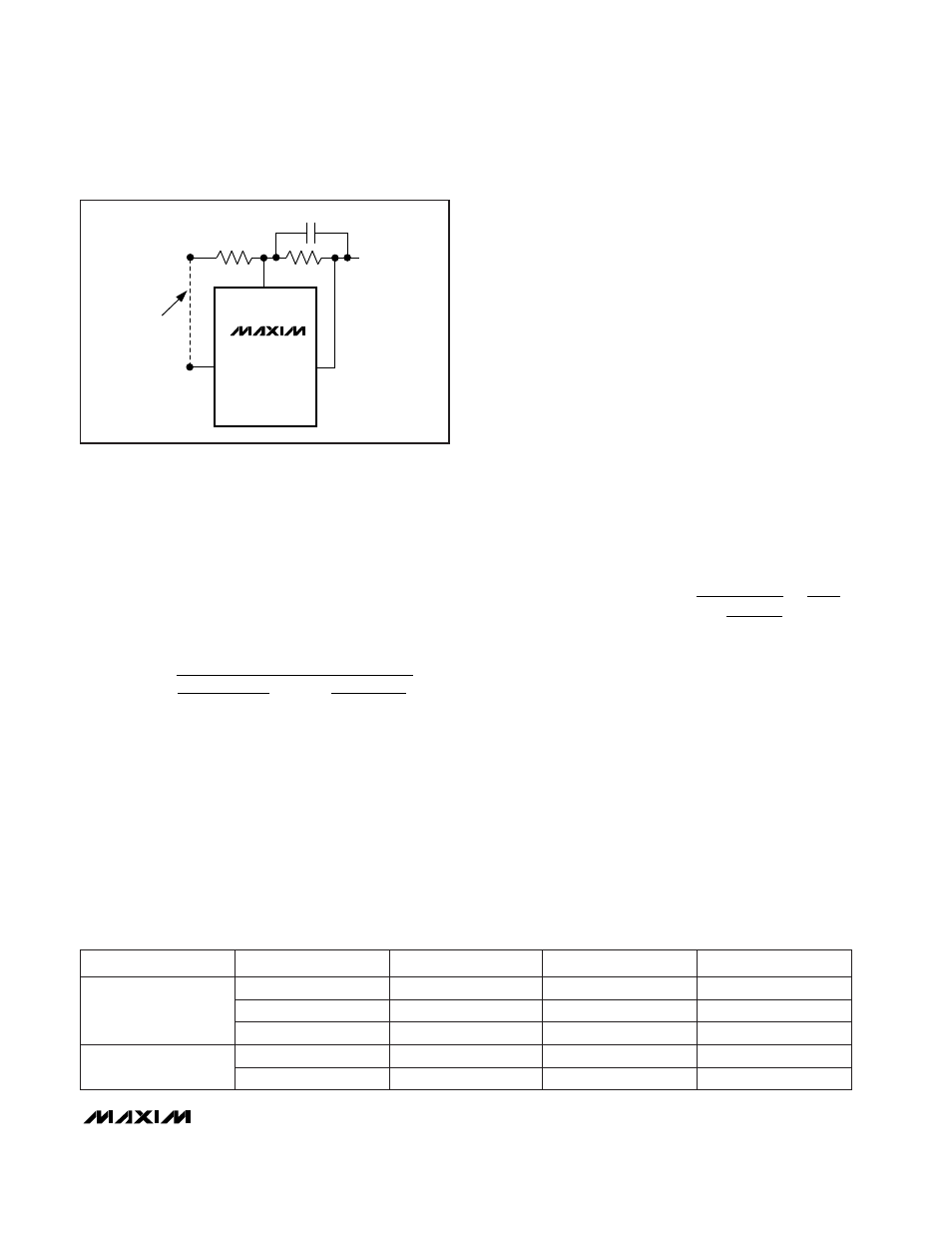
MAX868
IN
V
IN
V
REF
OPTIONAL
CONNECTION
*OPTIONAL
FEED-FORWARD
CAPACITOR
V
OUT
OUT
FB
C
C
*
R2
R1
Figure 4. Setting the Output Voltage Using Two External
Resistors