Typical performance characteristics, 0 mounting, Lm62 – Rainbow Electronics LM62 User Manual
Page 4
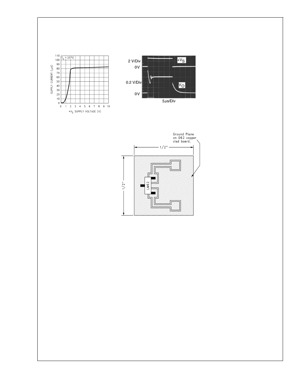
Typical Performance Characteristics
To generate these curves the LM62 was mounted to a
printed circuit board as shown in
Figure 2. (Continued)
1.0 Mounting
The LM62 can be applied easily in the same way as other
integrated-circuit temperature sensors. It can be glued or
cemented to a surface. The temperature that the LM62 is
sensing will be within about +0.2˚C of the surface tempera-
ture that LM62’s leads are attached to.
This presumes that the ambient air temperature is almost the
same as the surface temperature; if the air temperature were
much higher or lower than the surface temperature, the
actual temperature measured would be at an intermediate
temperature between the surface temperature and the air
temperature.
To ensure good thermal conductivity the backside of the
LM62 die is directly attached to the GND pin. The lands and
traces to the LM62 will, of course, be part of the printed
circuit board, which is the object whose temperature is being
measured. These printed circuit board lands and traces will
not cause the LM62’s temperature to deviate from the de-
sired temperature.
Alternatively, the LM62 can be mounted inside a sealed-end
metal tube, and can then be dipped into a bath or screwed
into a threaded hole in a tank. As with any IC, the LM62 and
accompanying wiring and circuits must be kept insulated and
dry, to avoid leakage and corrosion. This is especially true if
the circuit may operate at cold temperatures where conden-
sation can occur. Printed-circuit coatings and varnishes such
as Humiseal and epoxy paints or dips are often used to
ensure that moisture cannot corrode the LM62 or its connec-
tions.
The thermal resistance junction to ambient (
θ
JA
) is the pa-
rameter used to calculate the rise of a device junction tem-
perature due to its power dissipation. For the LM62 the
equation used to calculate the rise in the die temperature is
as follows:
T
J
= T
A
+
θ
JA
[(+V
S
I
Q
) + (+V
S
− V
O
) I
L
]
where I
Q
is the quiescent current and I
L
is the load current on
the output. Since the LM62’s junction temperature is the
actual temperature being measured care should be taken to
minimize the load current that the LM62 is required to drive.
Supply Voltage
vs Supply Current
DS100893-12
Start-Up Response
DS100893-22
DS100893-14
FIGURE 2. Printed Circuit Board Used
for Heat Sink to Generate All Curves.
1
⁄
2
" Square Printed Circuit Board
with 2 oz. Copper Foil or Similar.
LM62
www.national.com
4