Applications information – Rainbow Electronics MAX8715 User Manual
Page 9
MAX1790/MAX8715
Low-Noise Step-Up DC-DC Converters
_______________________________________________________________________________________
9
Output-Current Capability
The output-current capability of the MAX1790/MAX8715
is a function of current limit, input voltage, operating fre-
quency, and inductor value. Because of the slope com-
pensation used to stabilize the feedback loop, the duty
cycle affects the current limit. The output-current capa-
bility is governed by the following equation:
I
OUT(MAX)
= [I
LIM
x (1.26 - 0.4 x Duty) -
0.5 x Duty x V
IN
/ (f
OSC
x L)] x
η x V
IN
/ V
OUT
where:
I
LIM
= current limit specified at 65% (see the Electrical
Characteristics)
Duty = duty cycle = (V
OUT
- V
IN
+ V
DIODE
) /
(V
OUT
- I
LIM
x R
ON
+ V
DIODE
)
V
DIODE
= catch diode forward voltage at I
LIM
η = conversion efficiency, 85% nominal
Soft-Start
The MAX1790/MAX8715 can be programmed for soft-
start upon power-up with an external capacitor. When the
shutdown pin is taken high, the soft-start capacitor (C
SS
)
is immediately charged to 0.5V. Then the capacitor is
charged at a constant current of 4µA (typ). During this
time, the SS voltage directly controls the peak inductor
current, allowing 0A at V
SS
= 0.5V to the full current limit
at V
SS
= 1.5V. The maximum load current is available
after the soft-start cycle is completed. When the shut-
down pin is taken low, the soft-start capacitor is
discharged to ground.
Frequency Selection
The MAX1790/MAX8715s’ frequency can be user
selected to operate at either 640kHz or 1.2MHz.
Connect FREQ to GND for 640kHz operation. For a
1.2MHz switching frequency, connect FREQ to IN. This
allows the use of small, minimum-height external com-
ponents while maintaining low output noise. FREQ has
an internal pulldown, allowing the user the option of
leaving FREQ unconnected for 640kHz operation.
Shutdown
The MAX1790/MAX8715 are shut down to reduce the
supply current to 0.1µA when SHDN is low. In this
mode, the internal reference, error amplifier, compara-
tors, and biasing circuitry turn off while the n-channel
MOSFET is turned off. The boost converter’s output is
connected to IN by the external inductor and catch
diode.
Applications Information
Boost DC-DC converters using the MAX1790/MAX8715
can be designed by performing simple calculations for
a first iteration. All designs should be prototyped and
tested prior to production. Table 1 provides a list of
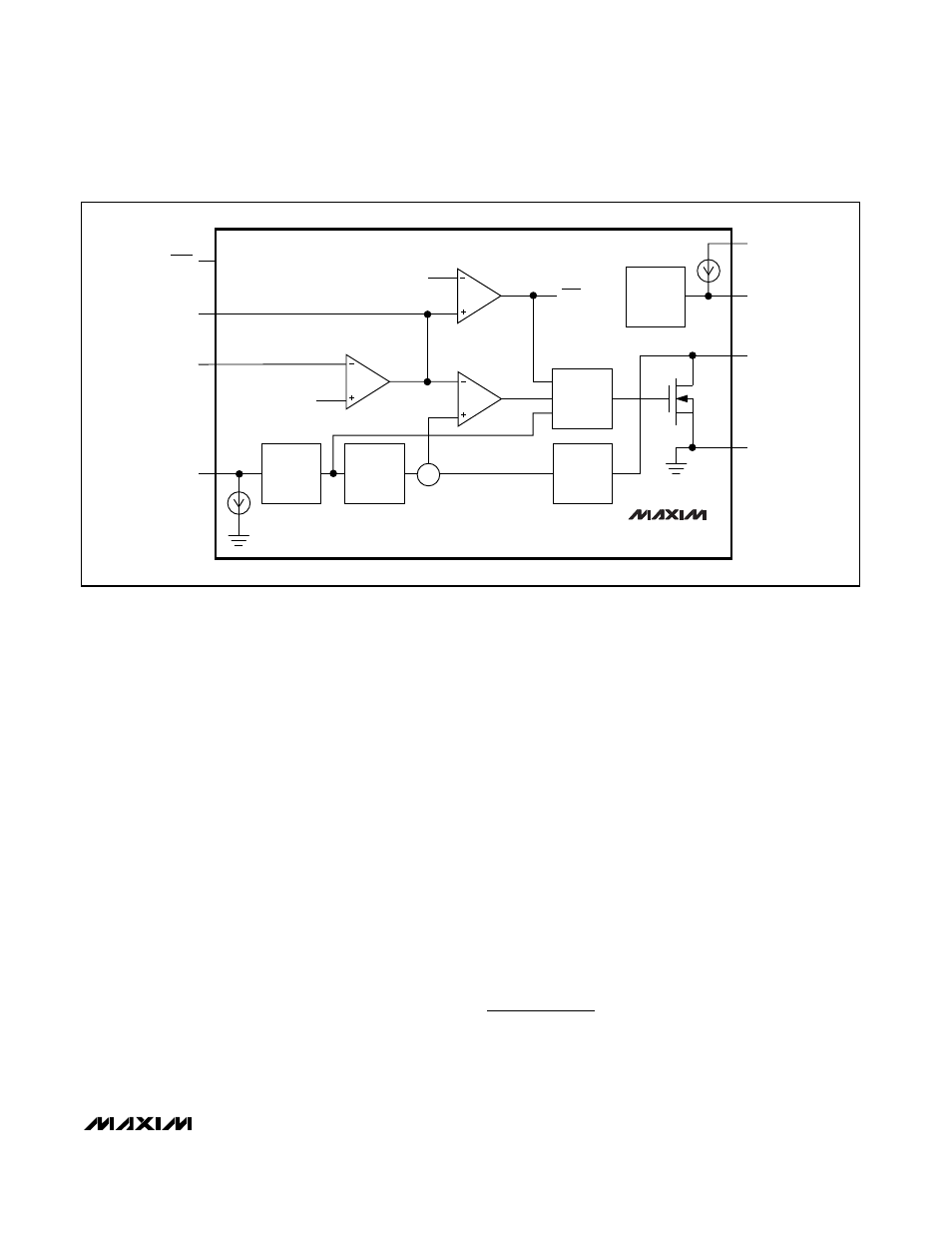
GND
LX
IN
FREQ
FB
COMP
4
µA
5
µA
N
ERROR
COMPARATOR
ERROR
AMPLIFIER
SKIP
COMPARATOR
SS
CLOCK
SKIP
BIAS
SHDN
MAX1790
MAX8715
Σ
CURRENT
SENSE
CONTROL
AND DRIVER
LOGIC
SOFT-
START
SLOPE
COMPEN-
SATION
OSCILLATOR
∞
1.24V
Figure 2. Functional Diagram