Rainbow Electronics MAX2051 User Manual
Page 4
MAX2051
SiGe, High-Linearity, 850MHz to 1550MHz
Up/Downconversion Mixer with LO Buffer
4
_______________________________________________________________________________________
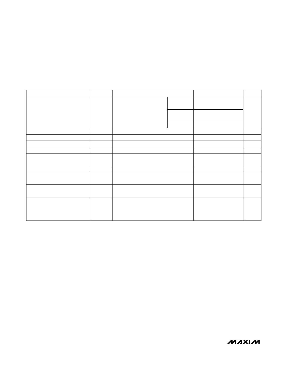
AC ELECTRICAL CHARACTERISTICS (DOWNCONVERTER OPERATION) (continued)
(
Typical Application Circuit, V
CC
= +4.75V to +5.25V, RF and LO ports are driven from 50
Ω sources, P
LO
= -3dBm to +3dBm,
P
RF
= 0dBm, f
RF
= 1000MHz to 1250MHz, f
LO
= 1200MHz to 2250MHz, f
IF
= 50MHz to 1000MHz, f
RF
< f
LO
, T
C
= -40°C to +85°C.
Typical values are at V
CC
= +5.0V, P
RF
= 0dBm, P
LO
= 0dBm, f
RF
=1200MHz, f
LO
= 1700MHz, f
IF
= 500MHz, T
C
=+25°C, unless oth-
erwise noted.) (Note 7)
PARAMETER
SYMBOL
CONDITIONS
MIN
TYP
MAX
UNITS
P
RF
=
-14dBm
87.5
101
P
RF
=
-10dBm
79.5
93
3LO-3RF Spurious Rejection
3 x 3
Single tone, f
RF
= 1200MHz,
50MHz < f
IF
< 1000MHz,
1250MHz < f
LO
< 2200MHz
(Notes 8, 9)
P
RF
= 0dBm
59.5
73
dBc
LO Leakage at RF Port
P
LO
= +3dBm (Notes 6, 8)
-33.5
-27.5
dBm
LO Leakage at IF Port
P
LO
= +3dBm (Notes 8, 9)
-26.3
-22.9
dBm
RF-to-IF Isolation
f
R F
= 1200M H z, P
L O
= + 3d Bm ( N otes 8, 9)
24
51
dB
RF Input Impedance
Z
RF
50
Ω
RF Input Return Loss
LO on and IF terminated with a matched
impedance
12
dB
LO Input Impedance
Z
LO
50
Ω
LO Input Return Loss
RF and IF terminated with a matched
impedance (Note 11)
11
dB
IF Output Impedance
Z
IF
Nominal differential impedance at the IC’s
IF outputs
50
Ω
IF Output Return Loss
RF ter m i nated i nto 50
Ω , LO d r i ven b y 50Ω
sour ce, IF tr ansfor m ed to 50
Ω si ng l e- end ed
usi ng exter nal com p onents show n i n the
Typ i cal Ap p l i cati on C i r cui t
15
dB