Synchronous rectification – Rainbow Electronics MAX1842 User Manual
Page 10
MAX1742/MAX1842
1A/2.7A, 1MHz, Step-Down Regulators with
Synchronous Rectification and Internal Switches
10
______________________________________________________________________________________
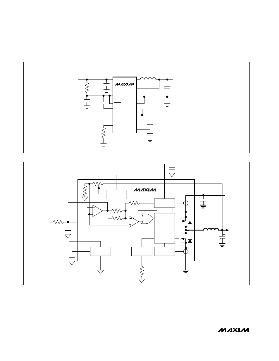
Synchronous Rectification
In a step-down regulator without synchronous rectifica-
tion, an external Schottky diode provides a path for cur-
rent to flow when the inductor is discharging. Replacing
the Schottky diode with a low-resistance NMOS syn-
chronous switch reduces conduction losses and
improves efficiency.
The NMOS synchronous-rectifier switch turns on follow-
ing a short delay after the PMOS power switch turns off,
thus preventing cross conduction or “shoot through.” In
V
CC
470pF
2.2
µF
1
µF
10
µF
10
Ω
FBSEL
0.01
µF
FEEDBACK
SELECTION
CURRENT
SENSE
PWM LOGIC
AND
DRIVERS
SS
IN
FB
V
IN
3.0V TO 5.5V
LX
PGND
TOFF
R
TOFF
GND
NOTE: HEAVY LINES DENOTE HIGH-CURRENT PATHS.
REF
REF
SUMMING
COMPARATOR
REF
REF
COMP
SKIP
SHDN
TIMER
V
IN
CURRENT
SENSE
G
m
C
OUT
V
OUT
MAX1742
MAX1842
Figure 2. Functional Diagram
TOFF
COMP
V
CC
FBSEL
SHDN
IN
PGND
GND
REF
SS
LX
FB
MAX1742
R
TOFF
1
µF
0.01
µF
L
2.2
µF
470pF
10
Ω
INPUT
C
IN
= 10
µF (MAX1742)
C
IN
= 33
µF (MAX1842)
OUTPUT
C
OUT
= 47
µF (MAX1742)
C
OUT
= 150
µF (MAX1842)
V
OUT
= 2.5V, FBSEL = V
CC
V
OUT
= 1.8V, FBSEL = REF
V
OUT
= 1.5V, FBSEL = FLOATING
Figure 1. Typical Circuit