Standard application circuits – Rainbow Electronics MAX1692 User Manual
Page 9
MAX1692
Low-Noise, 5.5V-Input,
PWM Step-Down Regulator
_______________________________________________________________________________________
9
Capacitor Selection
Choose input- and output-filter capacitors to service
inductor currents with acceptable voltage ripple. The
input-filter capacitor also reduces peak currents and
noise at the voltage source. In addition, connect a low-
ESR bulk capacitor (>10µF suggested) to the input.
Select this bulk capacitor to meet the input ripple
requirements and voltage rating, rather than capacitor
size. Use the following equation to calculate the maxi-
mum RMS input current:
I
RMS
= I
OUT
[V
OUT
(V
IN
- V
OUT
)]
1/2
·
V
IN
When selecting an output capacitor, consider the out-
put-ripple voltage and approximate it as the product of
the ripple current and the ESR of the output capacitor.
V
RIPPLE
=
[V
OUT
(V
IN
- V
OUT
)] /
[2
·
f
OSC
(L) (V
IN
)]
·
ESR
C2
where ESR
C2
is the equivalent-series resistance of the
output capacitor.
The MAX1692’s loop gain is relatively low, enabling the
use of small, low-value output filter capacitors. Higher
values provide improved output ripple and transient
response. Lower oscillator frequencies require a larger-
value output capacitor. When PWM/PFM is used, verify
capacitor selection with light loads during PFM opera-
tion, since output ripple is higher under these condi-
tions. Low-ESR capacitors are recommended.
Capacitor ESR is a major contributor to output ripple
(usually more than 60%). Ordinary aluminum-electrolyt-
ic capacitors have high ESR and should be avoided.
Low-ESR aluminum-electrolytic capacitors are accept-
able and relatively inexpensive. Low-ESR tantalum
capacitors are better and provide a compact solution
for space-constrained surface-mount designs. Do not
exceed the ripple-current ratings of tantalum capaci-
tors. Ceramic capacitors have the lowest ESR overall,
and OS-CON
™
capacitors have the lowest ESR of the
high-value electrolytic types.
It is generally not necessary to use ceramic or OS-CON
capacitors for the MAX1692; consider them only in very
compact, high-reliability, or wide-temperature applica-
tions where the expense is justified. When using very-
low-ESR capacitors, such as ceramic or OS-CON,
check for stability while examining load-transient
response. The output capacitor is determined by ensur-
ing that the minimum capacitance value and maximum
ESR values are met:
C2 > 2V
REF
(1 + V
OUT
/V
IN(MIN)
) / (V
OUT
·
R
SENSE
·
f
OSC
)
R
ESR
< (R
SENSE
)(V
OUT
) / (V
REF
)
where C2 is the output filter capacitor, V
REF
is the inter-
nal reference voltage of 1.25V, V
IN
(min) is the minimum
input voltage (2.7V), R
SENSE
is the internal sense resis-
tance of 0.1
Ω
, and f
OSC
is the internal oscillator fre-
quency (typically 750kHz). These equations provide the
minimum requirements. The value of C2 may need to
be increased for operation at duty-cycle extremes.
Tables 1 and 2 provide recommended inductor and
capacitor sizes at various external sync frequencies.
Table 3 lists suppliers for the various components used
with the MAX1692.
Standard Application Circuits
Figures 2 and 3 are standard application circuits opti-
mized for power and board space respectively. The cir-
cuit of Figure 2 is the most general of the two, and
generates 1.8V at 600mA.
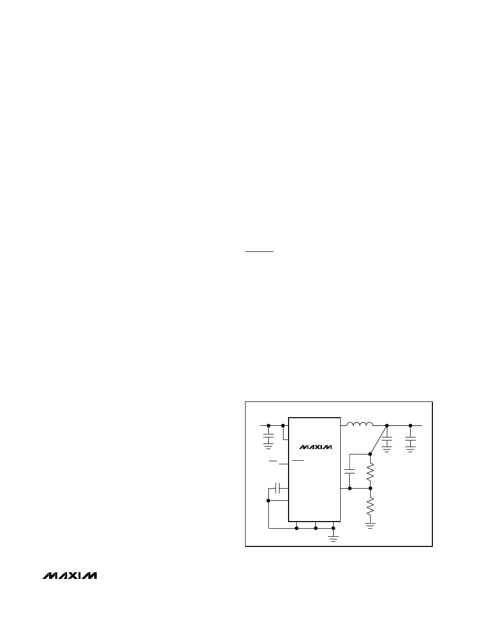
The circuit of Figure 3 is optimized for smallest overall
size. Cellular phones are using low voltage for base-
band logic and have critical area and height restric-
tions. This circuit operates from a single Li-ion battery
(2.9V to 4.5V) and delivers up to 200mA at 1.8V. It uses
small ceramic capacitors at the input and output and a
tiny chip inductor such as the NLC322522T series from
TDK. With the MAX1692 in a 10-pin µMAX package, the
entire circuit can fit in only 60mm
2
and have less than
2.4mm height.
LX
FB
IN
BP
REF
LIM
MAX1692
C5
4.7
µ
F
V
IN
+2.9V TO +4.5V
L1
10
µ
H
V
OUT
= 1.8V @ 200mA
C5
47pF
R1
138k
R2
301k
10
µ
F
10
µ
F
ON
/
OFF
C4
0.1
µ
F
GND
PGND
SYNC/
PWM
SHDN
C2
Figure 3. Miniaturized 200mA Output Circuit Fits in 60mm
2
OS-CON is a trademark of Sanyo Corp.