Electrical characteristics (continued), Electrical characteristics – Rainbow Electronics MAX1692 User Manual
Page 3
MAX1692
Low-Noise, 5.5V-Input,
PWM Step-Down Regulator
_______________________________________________________________________________________
3
Note 1:
Guaranteed by minimum and maximum duty-factor tests.
Note 2:
The following equation can be used to calculate FB accuracy for output voltages other than 1.232V:
(see Feedback Voltage vs. Load Current)
V
FB
= V
FB (NOMINAL)
- (Line Reg) (V
OUT
/ V
IN
- 0.23) / 0.77 - (
Load Reg
)(I
OUT
+ 0.5
·
I
RIPPLE
) / I
MAX
where: Line Reg = the line regulation
Load Reg = the load regulation
I
RIPPLE
= (1- V
OUT
/ V
IN
)
·
V
OUT
/ (f
OSC
·
L) where L is the inductor value
I
MAX
= 250mA (LIM = GND) or 600mA (LIM = IN)
Note 3:
Specifications to -40°C are guaranteed by design, not production tested.
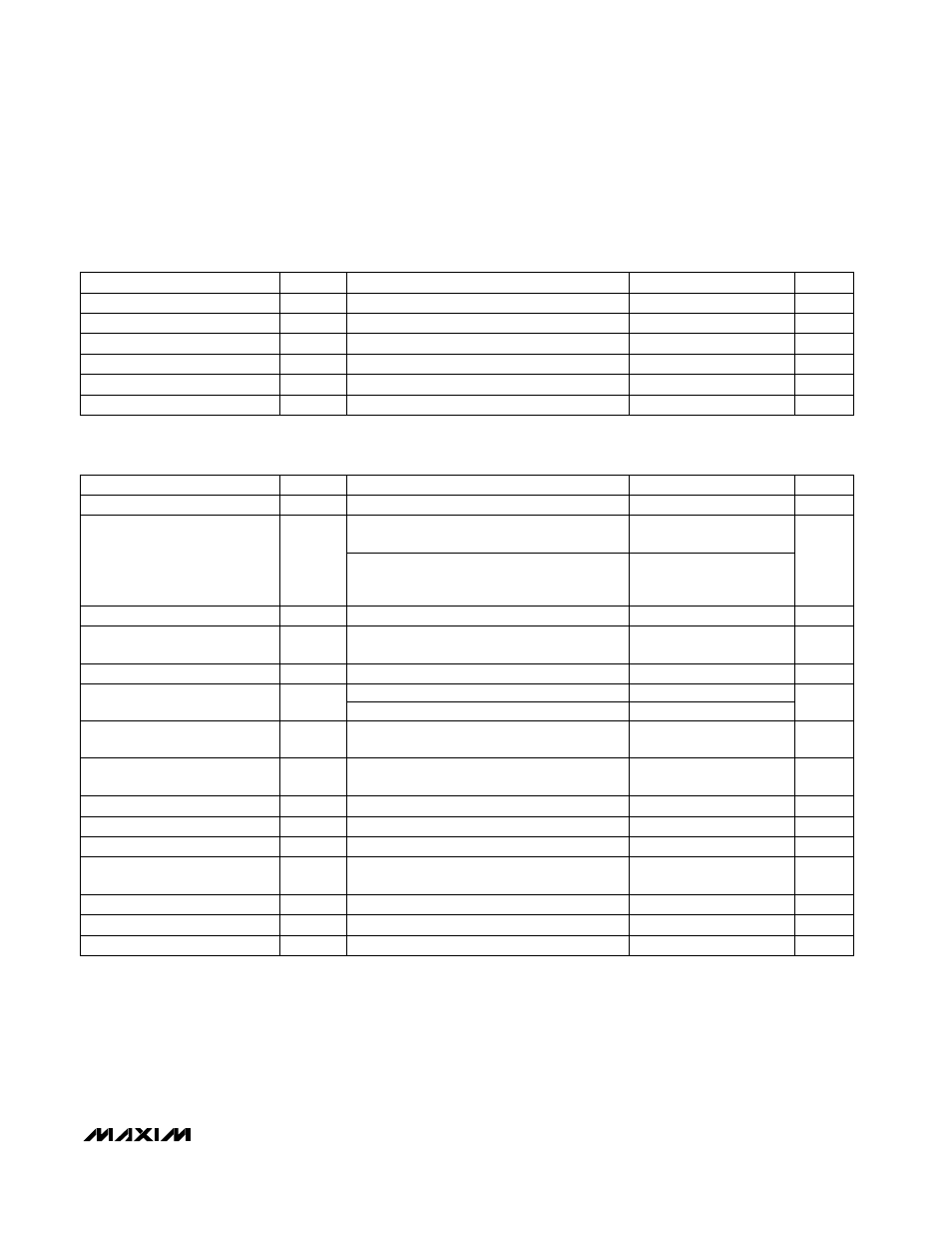
ELECTRICAL CHARACTERISTICS (continued)
(V
IN
= +3.6V, SYNC/PWM = GND, V
LIM
= 3.6V, SHDN = IN, circuit of Figure 2;
T
A
= 0°C to +85°C
, unless otherwise noted. Typical
values are at T
A
= +25°C.)
High or low
0
≤
I
REF
≤
50µA
SHDN, SYNC/PWM, LIM
CONDITIONS
ns
500
SYNC/PWM Minimum Pulse Width
mV
3
15
Reference Load Regulation
µA
-1
0.1
1
Logic Input Current
UNITS
MIN
TYP
MAX
SYMBOL
PARAMETER
(Note 1)
FB = OUT, V
IN
= V
LIM
= 2.7V to 5.5V,
I
OUT
= 0
SYNC/PWM = GND, LX = unconnected,
V
FB
= 1.4V
FB = OUT, V
IN
= V
LIM
= 5.5V, I
OUT
= 0
(duty cycle = 23%) (Note 2)
V
FB
=1.4V
LIM = IN
CONDITIONS
V
REF
V
IN
Output Adjustment Range
1.213
1.285
V
2.7
5.5
V
IN
Input Voltage Range
µA
140
Quiescent Current
V
1.213
1.285
V
FB
Feedback Voltage
nA
-50
50
I
FB
FB Input Current
A
0.7
1.6
P-Channel Current-Limit
Threshold
mA
N-Channel Current-Limit
Threshold
UNITS
MIN
MAX
SYMBOL
PARAMETER
ELECTRICAL CHARACTERISTICS
(V
IN
= +3.6V, SYNC/PWM = GND, V
LIM
= 3.6V, SHDN = IN, circuit of Figure 2,
T
A
= -40°C to +85°C
, unless otherwise noted.) (Note 3)
LIM = GND
SYNC/PWM = IN, FB = REF
-15
110
SHDN = LX = GND, includes LX leakage current
µA
10
Shutdown Supply Current
kHz
630
840
f
OSC
Oscillator Frequency
I
REF
= 0
V
1.230
1.268
V
REF
Reference Output Voltage
V
IN
rising, typical hysteresis is 85mV
V
2.3
2.5
UVLO
Undervoltage Lockout
Threshold
SHDN, SYNC/PWM, LIM
V
2
V
IH
Logic Input High
SHDN, SYNC/PWM, LIM
V
0.4
V
IL
Logic Input Low
SHDN, SYNC/PWM, LIM
µA
-1
1
Logic Input Current
0.3
0.9
SHDN, SYNC/PWM, LIM
V
0.4
V
IL
Logic Input Low
V
IN
rising, typical hysteresis is 85mV
V
2.3
2.4
2.5
UVLO
Undervoltage Lockout Threshold
SHDN, SYNC/PWM, LIM
V
2
V
IH
Logic Input High
FB = OUT, V
IN
= 2.7V to 5.5V,
I
OUT
= 0 to 600mA, LIM = IN or
I
OUT
= 0 to 250mA, LIM = GND
V
1.185
1.285
V
OUT
Output Voltage