Typical operating characteristics, Electrical characteristics (continued) – Rainbow Electronics MAX1619 User Manual
Page 4
0
6
3
9
12
50
5k
500k
50k
5M
500
50M
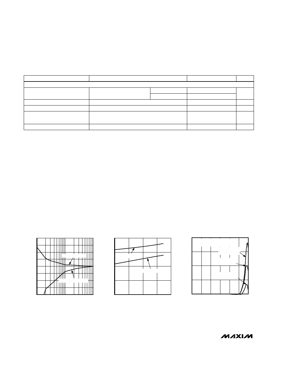
TEMPERATURE ERROR vs.
POWER-SUPPLY NOISE FREQUENCY
MAX1619-03
FREQUENCY (Hz)
TEMPERATURE ERROR (°C)
V
IN
= SQUARE WAVE APPLIED TO
V
CC
WITH NO 0.1
µ
F V
CC
CAPACITOR
V
IN
= 250mVp-p
REMOTE DIODE
V
IN
= 100mVp-p
LOCAL DIODE
V
IN
= 100mVp-p
REMOTE DIODE
-20
-10
-15
0
-5
10
5
20
15
TEMPERATURE ERROR
vs. PC BOARD RESISTANCE
MAX1619-01
LEAKAGE RESISTANCE (M
Ω
)
TEMPERATURE ERROR (°C)
1
10
100
PATH = DXP TO GND
PATH = DXP TO V
CC
(5V)
-2
-1
0
1
2
-50
50
100
0
150
TEMPERATURE ERROR
vs. REMOTE-DIODE TEMPERATURE
MAX1619-02
TEMPERATURE (°C)
TEMPERATURE ERROR (°C)
MOTOROLA MMBT3904
ZETEX FMMT3904
RANDOM
SAMPLES
__________________________________________Typical Operating Characteristics
(T
A
= +25°C, unless otherwise noted.)
MAX1619
Remote/Local Temperature Sensor with Dual-
Alarm Outputs and SMBus Serial Interface
4
_______________________________________________________________________________________
ELECTRICAL CHARACTERISTICS (continued)
(V
CC
= +3.3V,
T
A
= -55°C to +125°C
, configuration byte = XCh, unless otherwise noted.) (Note 4)
Note 1:
Guaranteed but not 100% tested.
Note 2:
Quantization error is not included in specifications for temperature accuracy. For example, if the MAX1619 device tempera-
ture is exactly +66.7°C, the ADC may report +66°C, +67°C, or +68°C (due to the quantization error plus the +1/2°C offset
used for rounding up) and still be within the guaranteed ±1°C error limits for the +60°C to +100°C temperature range
(Table 2).
Note 3:
A remote diode is any diode-connected transistor from Table 1. T
R
is the junction temperature of the remote diode. See
Remote Diode Selection
for remote diode forward voltage requirements.
Note 4:
Specifications from -55°C to +125°C are guaranteed by design, not production tested.
Note 5:
The SMBus logic block is a static design that works with clock frequencies down to DC. While slow operation is possible, it
violates the 10kHz minimum clock frequency and SMBus specifications, and may monopolize the bus.
Note 6:
Note that a transition must internally provide at least a hold time in order to bridge the undefined region (300ns max) of
SMBCLK’s falling edge.
CONDITIONS
UNITS
MIN
TYP
MAX
PARAMETER
STBY, SMBCLK, SMBDATA
2.2
Logic Input High Voltage
V
2.4
STBY, SMBCLK, SMBDATA; V
CC
= 3V to 5.5V
V
0.8
Logic Input Low Voltage
ALERT, OVERT forced to 5.5V
µA
1
ALERT, OVERT Output High
Leakage Current
Logic inputs forced to V
CC
or GND
µA
-2
2
Logic Input Current
V
CC
= 3V
V
CC
= 5.5V
ALERT, OVERT, SMBDATA forced to 0.4V
mA
6
Logic Output Low Sink Current
SMBus INTERFACE