Table 6. status-byte bit assignments, Table 7. conversion-frequency control byte – Rainbow Electronics MAX1619 User Manual
Page 14
MAX1619
Remote/Local Temperature Sensor with Dual-
Alarm Outputs and SMBus Serial Interface
14
______________________________________________________________________________________
Write-Once Protection
Write-once protection allows the host BIOS code to
configure the MAX1619 in a particular way, and then
protect that configuration against data corruption in the
host that might cause spurious writes to the MAX1619.
In particular, write protection allows a foolproof over-
temperature override that forces the fan on 100% via
OVERT independent of the host system. The write-pro-
tection bit (bit 4), once set high, can’t be reset to low
except by a hardware power-on reset. A SPOR (soft-
ware POR) will not reset this bit.
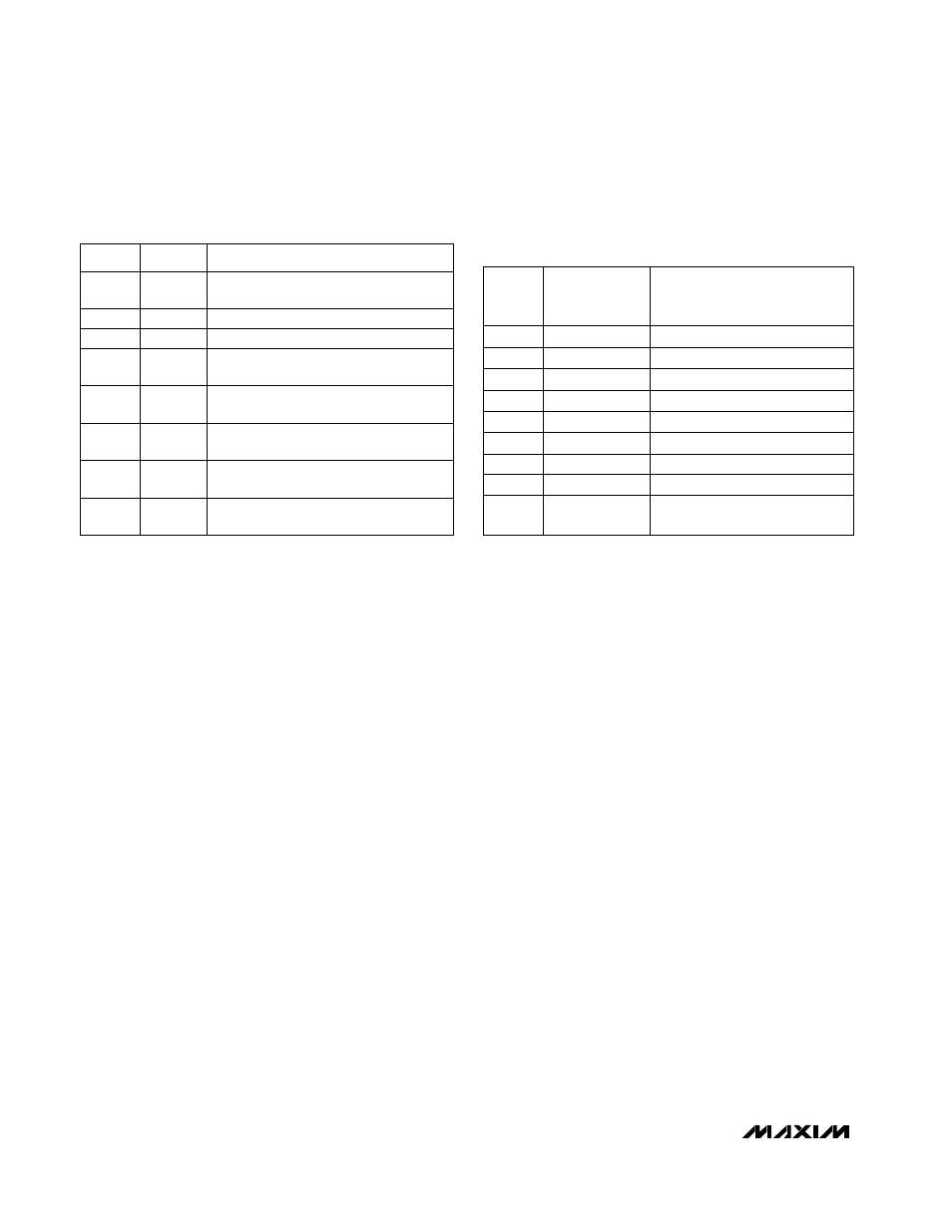
Status Byte Functions
The status byte register (Table 6) indicates which (if
any) temperature thresholds have been exceeded. This
byte also indicates whether or not the ADC is converting
and whether there is an open circuit in the remote diode
DXP–DXN path. The status byte is cleared by any suc-
cessful read of the status byte, unless the fault persists.
The status of bit1 (OVER) follows the state of OVERT
exactly. Note that the ALERT interrupt latch is not auto-
matically cleared when the status flag bit is cleared.
When autoconverting, if the T
HIGH
and T
LOW
limits are
close together, it’s possible for both high-temp and low-
temp status bits to be set, depending on the amount of
time between status read operations (especially when
converting at the fastest rate). In these circumstances, it’s
best not to rely on the status bits to indicate reversals in
long-term temperature changes. Instead, use a current
temperature reading to establish the trend direction.
Conversion Rate Byte
The conversion rate register (Table 7) programs the time
interval between conversions in free-running autoconvert
mode. This variable rate control reduces the supply cur-
rent in portable-equipment applications. The conversion
rate byte’s POR state is 02h (0.25Hz). The MAX1619
looks only at the 3 LSB bits of this register, so the upper 5
bits are “don’t care” bits, which should be set to zero. The
conversion rate tolerance is ±25% at any rate setting.
Valid A/D conversion results for both channels are avail-
able one total conversion period (125ms nominal, 156ms
maximum) after initiating a conversion, whether conver-
sion is initiated via the RUN/STOP bit, hardware STBY
pin, one-shot command, or initial power-up. Changing the
conversion rate can also affect the delay until new results
are available (Table 8).
Manufacturer and Device ID Codes
Two ROM registers provide manufacturer and device ID
codes (Table 4). Reading the manufacturer ID returns
4Dh, which is the ASCII code “M” (for Maxim). Reading
the device ID returns 04h, indicating a MAX1619 device.
If READ WORD 16-bit SMBus protocol is employed
(rather than the 8-bit READ BYTE), the least significant
byte contains the data and the most significant byte con-
tains 00h in both cases.
Slave Addresses
The MAX1619 appears to the SMBus as one device
having a common address for both ADC channels. The
device address can initially be set to one of nine differ-
ent values by pin-strapping ADD0 and ADD1 so that
more than one MAX1619 can reside on the same bus
without address conflicts (Table 9).
Table 6. Status-Byte Bit Assignments
*
The HIGH and LOW temperature alarm flags stay high until
cleared by POR or until status register is read.
RFU
6
Reserved for future use.
A high indicates that the ADC is busy
converting.
FUNCTION
RFU
5
Reserved for future use.
RHIGH*
4
A high indicates that the remote high-
temperature alarm has activated.
RLOW*
3
A high indicates that the remote low-
temperature alarm has activated.
OPEN*
2
A high indicates a remote-diode conti-
nuity (open-circuit) fault.
OVER
1
BUSY
7
(MSB)
This bit follows the state of the OVERT
pin exactly, in real time (unlatched).
RFU
0
(LSB)
Reserved for future use.
BIT
NAME
Table 7. Conversion-Frequency Control
Byte
0.125
01h
33
30
AVERAGE SUPPLY
CURRENT
(µA typ, at V
CC
= 3.3V)
0.25
02h
35
0.5
03h
48
1
04h
70
2
05h
128
4
06h
0.0625
00h
225
8
07h
425
RFU
08h to
FFh
—
DATA
CONVERSION
FREQUENCY
(Hz)